Understanding When to Use a Rotary vs. Reciprocating Seal
Key Highlights
- The type of motion which occurs in hydraulic cylinders places different design requirements on their O-rings and often dictates whether a rotary or reciprocating option should be used for these seals.
- Squeeze, pressure limit, and groove location are some of the design factors that can change based on where an O-ring will be used.
- Calculating surface speed is the very first step to take to determine whether a design even requires use of an O-ring. From there, designers can the decide if a rotary or reciprocating seal type should be utilized.
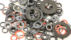
Take an O-ring that has sealed a hydraulic cylinder rod without complaint, put the same seal on a rotating shaft in the same fluid at the same temperature, and it can cook itself in a fraction of the service life.
Nothing changed except the type of motion, yet that change required different seal design limits and gland specifications, including:
- squeeze,
- pressure limits,
- groove location,
- installed stretch, and
- allowable surface speed.
O-rings used for dynamic sealing can be categorized as either a rotary seal — for rotating or oscillating components — or a reciprocating seal — which is used to seal a gap between two parts.
However, most of the time seals for both types of motion tend to get filed under "dynamic sealing," which is where the trouble starts. That’s because they actually have different sealing requirements, necessitating use of either a rotary or reciprocating seal.
Some manufacturers do differentiate between the two sealing types. For instance, in Parker Hannifin's O-Ring Handbook, it uses a separate design chart for each seal type. Chart 5-2 for industrial reciprocating glands and Chart 5-4 for rotary, and the recommended values barely overlap.
But because this differentiation is not always spelled out, it is important to understand how changes in motion translate to seal design. This article outlines how seal design limits and gland specifications change based on the type of motion occurring in a hydraulic component so you can better determine if a rotary or reciprocating seal should be used.
Surface Speed: Calculate It Before Anything Else
Before touching a seal catalog to determine whether to use a rotary or reciprocating seal, it is necessary to first convert shaft speed into surface speed at the seal. This can be done using the following equation:
Surface speed (ft./min.) = 0.26 x shaft diameter (in.) x rpm
A 2 in. shaft at 500 rpm gives 260 ft./min., or 1.3 m/s. The same shaft at 1,750 rpm gives 910 ft./min., 4.6 m/s. That one number decides whether an O-ring belongs in the design at all. (0.26 is pi over 12.)
Parker's rotary chart bounds that speed by cross-section. A 1/16 in. section is good for 1,500 ft./min., about 7.6 m/s. Step up to 3/32 in. and the ceiling falls to 600 ft./min., roughly 3 m/s. At 1/8 in. it is down to 400 ft./min., near 2 m/s.
Bigger cross-section, lower speed limit. That is backwards from how most of us think about seals, where a heavier section reads as a more robust part. Rubber is a poor conductor, the frictional heat is made right at the sliding interface, and the only way out is through the shaft and the housing, so a thick section just runs hotter in the middle and the chart derates it accordingly.
There's a floor too. Below 200 ft./min. Parker's rotary chart sends you back to the reciprocating chart. Slow rotation, dimensionally, is a reciprocating problem.
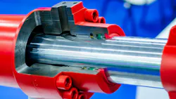
Squeeze: Rotary Glands Run Almost None
Squeeze is the number most often carried straight over from a reciprocating design, and it is the one that moves furthest.
Reciprocating glands run 15-25% squeeze at 1/16 in. cross-section, 10-17% at 3/32 in., 9-16% at 1/8 in. Rotary glands run 0-11%, 1-8.5%, and 0-7% across the same three sections.
Those percentages are what falls out of the published gland depth range against the cross-section tolerance, so they're stack extremes on both charts and can be compared directly. The 11% is what a worst-case rotary stack reaches, not a target. A rotary gland gets designed close to zero.
The reason is that heat input scales with contact pressure, and rotary service gives the heat nowhere to go. In a cylinder the seal traverses a fresh length of rod on every stroke and drags a lubricant film along with it. On a rotating shaft the same band of rubber rides the same circular track forever. So you take contact pressure down to whatever still seals, and no further.
Designing that close to zero has a price: tolerance stack-up stops being a rounding error. Parker pairs those squeeze values with a maximum eccentricity of 0.002 in. TIR, opening only to 0.003 in. on the 1/8 in. sections, and with a minimum bearing length next to the groove: 0.700 in. at 1/16 in. cross-section, 1.390 in. at 1/8 in. A near-zero-squeeze gland is only as good as the concentricity of the parts holding it.
Pressure Limits to Watch
Parker publishes industrial reciprocating seal gland data to 103.5 bar (1,500 psi) without backup rings. Rotary gland data stops at 55.2 bar (800 psi).
The rotary chart's diametral clearances of 0.012-0.016 in. are based on a minimum 80 Shore A compound at that 800-psi ceiling. Drop a 70-durometer ring into a seal gland dimensioned from that chart and you are outside the basis of the numbers you used.
On the reciprocating side the equivalent step above 1,500 psi is backup rings, which need a wider groove.

Groove Location and Installed Stretch: Two Rotary-Only Rules
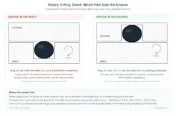
Parker's rotary chart carries a one-line note that works as a hard rule: due to the effect of centrifugal force, do not locate the seal groove in the shaft.
Cut the gland into the housing and the ring stays with the stationary part while the shaft turns underneath its I.D. (inner diameter). Cut it into the shaft and the ring spins with the shaft, and centrifugal force pushes it out against the stationary bore, piling contact load and heat onto the one interface already doing all the work.
Rod glands and piston glands are both routine on a cylinder. On a rotating shaft that symmetry is gone.
The other rotary-only rule is that the ring must never go on in stretch. Some installed stretch is normal to ensure an O-ring securely fits over a reciprocating piston. On a turning shaft it has a name and a well-documented failure chain.
The Gough-Joule effect describes what a stretched elastomer does when it gets hot: it contracts instead of expanding. Parker's handbook works the example directly. An O-ring whose I.D. is smaller than the shaft sits in tension. Friction heats it. Heat makes it contract. Contraction raises contact pressure, which makes more heat. It runs away until the ring seizes the shaft, and you get the part back with a hard, brittle surface.
The European edition of Parker's O-ring handbook puts the ring I.D. 1-3% over the shaft and lets the outer part of the gland do the compressing. Squeeze it inward from the housing. Never stretch it out over the shaft.
Counterface: Lay Matters as Much as Roughness
Reciprocating gland drawings call for 16 RMS on the dynamic sealing surface and 32 RMS on the groove walls, opening up to 63 RMS on the groove bottom when a backup ring goes in. Amplitude is the whole story.
On a rotating counterface, direction matters as much as amplitude. DIN 3760 sets a floor of 45 HRC, wants 60 HRC by 10 m/s and calls for Ra 0.2 to 0.8 micrometers; Trelleborg's own rotary shaft seal data tightens the roughness band to Ra 0.2 to 0.5 and asks for 55 HRC, or 600 HV, to a minimum hardened depth of 0.3 mm.
The part that gets left off drawings is the machining method. Spiral grinding marks act like a screw thread and pump fluid straight across the seal, so the shaft has to be plunge ground. A shaft that measures perfectly for roughness will still leak if the lay is wrong, and polishing it isn't a fix. Polished surfaces generate more friction and more heat than plunge ground ones.
When an O-Ring is the Wrong Component
The two rotary options trade pressure against speed almost exactly opposite to one another. A rotary O-ring gland is good to 55.2 bar (800 psi) but only about 7.6 m/s, and that's at the smallest cross-section.
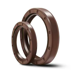
Go the other way and an elastomeric lip seal to DIN 3760 type A is rated for essentially no pressure, capped around 0.05 MPa, but it takes more speed. Trelleborg rates its DIN 3760 type A seals to 10 m/s, material dependent. That is not much headroom over the O-ring gland.
Real rotary speed comes from purpose-built designs: 40 m/s from Trelleborg's FKM (Fluorkautschukmaterial [i.e. fluorine rubber material])-lipped high-speed type, 60 m/s and beyond in PTFE (polytetrafluoroethylene). How much of that a given compound actually delivers varies enough between makers that the number is worth pulling out of Trelleborg's or SKF's own catalog rather than off a summary table, and catalog maxima in this corner of the market have a way of being quoted as though they stack.
So the O-ring is the pressure component and the lip seal is the speed component. If an application genuinely needs both, neither one applies and the answer is a PTFE-based rotary seal, where special designs go far past anything an elastomer will do.
One caveat that applies to all of these ratings: published maxima are individual limits and can't be claimed at the same time. A speed number assumes the pressure, temperature and lubrication are all cooperating.
Failure Modes to Watch For: Heat Damage Often Reads as Chemical Damage
Failure for reciprocating and rotary parts impact hydraulic sealing technology in different ways, each of which is important to understand to ensure larger downtime issues are prevented from occurring.
Reciprocating service produces spiral failure. Some segments of the ring roll while the ones next to them slide, twisting the section against itself until the surface tears open.
Parker puts the blame mainly on out-of-roundness and eccentricity varying the compression around the circumference, and the fixes are what you'd expect: less eccentricity, better surface finish, real lubrication, a harder ring. Gap extrusion is the other reciprocating signature and it tracks pressure and clearance.
Rotary service fails thermally. You get a hardened, glazed surface, often with the ring seized or turning in its own groove. Read that as a chemical compatibility problem and the next step is a more expensive polymer, which replaces the part without touching the cause. I'd rather see the money go into the shaft finish.
Final Takeaways for Specifying Rotary and Reciprocating Seals
When it comes time to create the final design drawing and specify the hydraulic sealing technologies to use, be sure to follow these steps.
Surface speed gets calculated before anything else:
0.26 x shaft diameter in inches x rpm.
Under 200 ft./min., design it as a reciprocating gland and move on.
Check that speed against cross-section rather than against one global limit, since a section change on its own can pull a marginal design back into range, and take the smallest workable section while you're in there. A metric O-ring size chart will show which standard sections actually exist at your shaft diameter before you dimension a gland around one of them. Then confirm the pressure sits inside 55.2 bar, and that the compound is 80 Shore A or harder if you are using the published clearances.
The gland goes in the housing, the ring I.D. sits 1-3% over the shaft, squeeze comes off the rotary chart, and eccentricity and bearing length get tightened to suit a gland with no squeeze to spare. The counterface gets specified as a rotary counterface, which means hardness, roughness band and plunge ground are all called out on the drawing rather than left to the machine shop.
If the speed and pressure combination lands outside the rotary O-ring envelope, change the component, not the compound. Switching formulations doesn't move Parker's 1,500 ft./min. chart limit.
None of this is hard to design around. It is hard to catch afterward, because a seal that died of heat looks a lot like a seal that died of chemistry, and the first thing anybody tries is a better material.
Checking the motion against the right design chart takes a few minutes at the specification stage and rules out a category of failures that no compound upgrade was going to solve.
This article was written and contributed by Xing Hong, founder of WRKR Seal.