Moving a Hydraulic Power Unit to 60 Hz: A Checklist for Ensuring Performance
Key Highlights
- Machine builders who develop hydraulic power units for markets using a 50 Hz power supply and want to also sell those units into markets using 60 Hz need to consider various performance changes that can occur before doing so.
- The electric motor of a power unit designed for a 50 Hz power supply will run about 20% faster on 60 Hz which impacts flow, power demand and load on downstream components.
- There are several steps that should be followed, such as checking actuator speeds and recalculating pump flow to meet motor speed, to ensure a hydraulic power unit will perform as desired in a 60 Hz market.
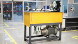
Machine builders in Europe regularly sell the same machine into North America and other 60 Hz markets. And the hydraulic power unit (HPU) in these machines is often treated as a detail: same pump, same valves, a different motor plate.
However, those machines are typically designed to operate on a 50 Hz power supply. A power unit that works well in Europe will not behave the same on a 60 Hz supply. The motor runs about 20% faster, and that changes flow, power demand and the load on every component downstream.
In this article, author Don van Wallinga from Hydrauliek24 B.V. explains what changes, why, and what to check when supplying an HPU designed for a 50 Hz power supply to a market using 60 Hz.
Follow These Steps to Ensure HPU Performance on a 60 Hz Power Supply
If selling an HPU designed for a 50 Hz power supply to a market that uses 60 Hz, it is important to go through the following checklist before sending the power unit into a new market:
- Recalculate pump flow at the 60 Hz motor speed.
- Check actuator speeds and cycle times against the machine's requirements.
- Recalculate drive power at the working pressure.
- Size the motor on its 60 Hz rating at the actual supply voltage.
- Confirm the required certification (for example UL) and efficiency class on the motor itself.
- Check the pressure the motor can sustain at the new flow.
- Check the pump's maximum speed and the suction line.
- Check valves, filters and lines for the higher flow and pressure drop.
- Check heat balance: reservoir, cooler and idle circulation.
None of these steps are difficult, but skipping one of them is how a unit that ran well in Europe ends up running hot, slow or out of specification on its first 60 Hz job site.
Outlined below are some of the changes that can occur when a unit goes to a 60 Hz market and tips for how the above steps can be used to determine whether an HPU design will perform as desired in that market.
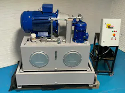
The Motor Runs About 20% Faster
The electric motor in an HPU designed for a 50 Hz power supply will run roughly 20% faster when it goes to a 60 Hz market.
The speed of an induction motor follows the supply frequency. The synchronous speed is:
n (rpm) = 120 × f (Hz) / number of poles
A four-pole motor has a synchronous speed of 1,500 rpm at 50 Hz and 1,800 rpm at 60 Hz. Under load, slip brings the real speed down a little: a typical 4 kW four-pole motor runs at about 1,430 rpm at 50 Hz and about 1,720 rpm at 60 Hz.
Either way, the ratio is close to 60/50 = 1.2.
A Fixed Pump Delivers About 20% More Flow
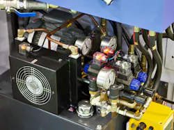
Use of a fixed-displacement pump with the HPU means that when the unit moves to a 60 Hz market there will be roughly 20% more flow.
The flow of a fixed-displacement pump is proportional to its speed:
Q (l/min) = Vg (cc/rev) × n (rpm) / 1000
A 15-cc gear pump delivers about 15 × 1,430 / 1000 = 21.5 l/min at 50 Hz and about 15 × 1,720 / 1000 = 25.7 l/min at 60 Hz. These are theoretical values; internal leakage makes real flow slightly lower, especially at high pressure and temperature.
The direct result is that every actuator moves about 20% faster. Cylinders extend and retract faster, hydraulic motors turn faster, and cycle times drop. That can be welcome, but it can also mean harder end-of-stroke impacts, a lowering speed that is no longer acceptable, or a process that no longer matches the timing of the rest of the machine.
Power Demand Rises with Flow but Torque Does Not
Alongside increases in flow are typically increases in power demand for the HPU’s fixed-displacement pump although its torque does not go up.
Hydraulic power is calculated as pressure times flow. With an assumed overall efficiency of about 90%, the drive power is:
P (kW) = p (bar) × Q (l/min) / 540
At the same working pressure, 20% more flow means 20% more power. It helps to look at torque as well. The torque a pump needs depends on displacement and pressure only:
T (Nm) = Vg (cc/rev) × p (bar) / (20 × π)
So, the pump needs the same torque at 60 Hz as at 50 Hz; it simply turns faster, and power is torque times speed. Whether the motor can supply that extra power depends on its 60 Hz rating, which brings us to the motor itself.
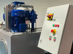
Check the Motor's 60 Hz Rating, Not Just its 50 Hz Rating
A motor wound for 400V at 50 Hz keeps roughly the same magnetic conditions at 480V at 60 Hz because voltage and frequency rise by the same factor. The motor then delivers about the same torque at a 20% higher speed, so about 20% more power at the same current.
The motor catalogue Hydrauliek24 works with shows exactly that on its sample nameplate: 22 kW at 400V/50 Hz becomes 26.4 kW at 480V/60 Hz. On a 60 Hz supply without the matching voltage increase, that extra power is not available.
The rule is simple: size the motor on its 60 Hz rating at the actual supply voltage, never on the 50 Hz figure.
Certification is the second part of the motor question. In one of Hydrauliek24’s customer projects, a machine that had already been delivered in Europe was ordered by an end user in the United States. The customer required a UL-certified motor with efficiency class IE3.
Not every motor in a standard range carries UL certification, so the Hydrauliek24 team selected a specific product line and checked the UL marking on the motor before assembly. That check is worth building into the process: a missing mark is easy to overlook in the workshop and expensive to discover on site.
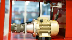
Understand That a Calculated Power Limit is Not a Guaranteed Working Pressure
Rearranging the power formula gives the pressure a motor can sustain at a given flow:
p (bar) = P (kW) × 540 / Q (l/min)
Another customer project involved a power unit for food processing machines, specified for 480V/60 Hz with a UL-certified IE3 motor of 4 kW (its 50 Hz rating), a 15-cc gear pump and a working pressure of 90 bar.
At 50 Hz, with 4 kW and 21.5 l/min, using the formula above gives about 101 bar. Had the motor delivered only its 4 kW at 60 Hz, the higher flow of 25.7 l/min would have brought that down to about 84 bar, below the working pressure.
Because the motor was wound for 480V/60 Hz, its 60 Hz output is about 4.8 kW, and the limit is back at about 101 bar. The pump needs the same torque, and the motor supplies the same torque; only the speed has changed.
Two cautions apply:
- First, the 540 divisor assumes 90% overall efficiency; a worn pump, hot oil or long narrow lines lower it.
- Second, the result is the pressure the motor can drive, not the maximum system pressure.
The relief valve setting and the ratings of the pump, hoses, valves and actuators still set the limits. Treat the calculated figure as a check on the motor, not as a design pressure.
Verify the Pump's Permitted Speed and Inlet Conditions
Most gear pumps accept 1,720 rpm without difficulty, but the datasheet decides, especially for larger displacements. The suction side matters just as much: 20% more flow means 20% higher oil velocity in the suction line. A line that was adequate at 50 Hz may now be at the edge of cavitation, particularly with cold oil.
In the first customer project referenced, the higher flow was acceptable for the application and the pump did not need to change. That is a conclusion to reach by checking, not by assuming.
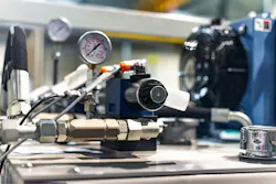
Check How Flow Will Impact Valves, Filters and Heat
Every component the flow passes through sees about 20% more of it. Pressure drop rises roughly with the square of flow, so 1.2 × 1.2 gives about 44% more pressure drop across directional valves, flow controls, filters and return lines.
Check that:
- directional valves and modular blocks are rated for the new flow;
- flow control and throttle settings still give acceptable speeds;
- filters are sized for the new flow without excessive pressure drop;
- the reservoir and any cooler can handle the extra heat.
Heat deserves attention too. Any flow that is throttled or goes over the relief valve turns into heat, and there is now more of it. In the food processing project, each unit was fitted with an oil cooler with a fixed 60 C (140 F) thermostat.
Understanding how performance of a hydraulic power unit changes when it goes from a 50 to 60 Hz power supply and following this guide to validate the unit’s performance at 60 Hz will help you better ensure an optimized customer experience.
This article was written and contributed by Don van Wallinga, E-commerce Specialist at Hydrauliek24 B.V.
About the Author
Don van Wallinga
E-commerce Specialist at Hydrauliek24 B.V.
Don van Wallinga is E-commerce Specialist at Hydrauliek24 B.V. in Enschede, the Netherlands, which designs and builds hydraulic power units in its own workshop.