Pop the Cavitation Bubble in Hydraulic Systems
This file type includes high resolution graphics and schematics when applicable.
Cavitation, defined simply as the formation of bubbles in a liquid, can have detrimental effects on a hydraulic pump. In an incorrectly designed hydraulic system, a vacuum may form on the hydraulic fluid, pulling trapped air out of the fluid to form small bubbles.
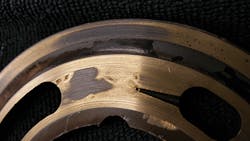
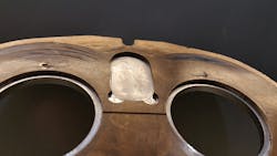
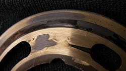
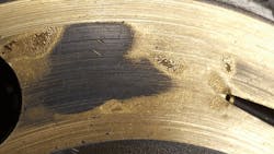
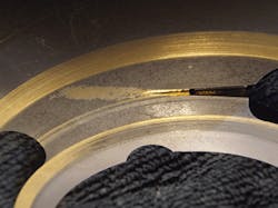
A variety of factors within the system could produce such a vacuum. When fluid enters the hydraulic pump and is compressed, the small air bubbles implode on a molecular level. Each implosion is extremely powerful and can remove material from the inside of the pump until it is no longer functional. Cavitation can destroy brand new pumps in a matter of minutes, leaving signs of physical damage including specific wear patterns. The process of cavitation destroying a hydraulic pump also has a distinctly audible sound similar to a growl.
The good news is that cavitation need not be a common problem in hydraulic systems. A few design flaws are largely responsible for causing cavitation: improper configuration of pump suction lines and the use of suction-line filters or strainers. To prevent these causes of cavitation and ensure the creation of a quality hydraulic system with a long, productive life, seven design elements must be properly executed:
- Correctly design the hydraulic reservoir.
- Use a breather filter on the reservoir.
- Install properly sized and configured suction lines.
- Remove any suction-line filtration.
- Use a properly sized pump.
- Maintain proper fluid temperature.
- Use a flooded suction for the pump.
What Triggers Cavitation?
As previously stated, the leading causes of cavitation in hydraulic systems are improper pump suction-line configurations and the use of filters or strainers. When configuring a pump suction line, the goal is to minimize the pressure drop into pump. The primary strategy to accomplish this low pressure drop is to make the hoses as short as possible and use the least amount of fittings on the line. When designing a hydraulic system, engineers will often fail to consider the length of the hoses required to connect the reservoir to the pump. The longer the path that the hydraulic fluid must travel through, the more likely it is to experience a pressure drop. Furthermore, each fitting on a hose adds an additional pressure drop on the line, further increasing the risk of cavitation.
In addition to improper pump suction-line configurations, suction-line filters or strainers can be a leading cause of cavitation. These filters are often placed under the oil reservoir, and thus are rarely serviced properly due to their inconvenient location. With this configuration, the entire reservoir has to be drained and disassembled in order to the reach the filter, so this necessary task is often neglected. As the filter becomes increasingly full of debris over time due to a lack of regular maintenance, not enough fluid will flow to the pump, and cavitation will occur.
Such causes of cavitation can be prevented using a series of correct design practices based on the specific needs and functions of a hydraulic system. Many systems are unique, so an experienced engineer with a firm grasp on each of these concepts must ensure the proper installation and maintenance of a hydraulic system.
Correct Reservoir Design
Air bubbles in hydraulic fluid first originate is in the reservoir. New oil being introduced into the reservoir can cause turbulent flow, stirring up the oil and introducing air into the fluid, which can lead to cavitation. A correctly designed reservoir tank will prevent this issue.
The best way to prevent turbulent flow from the introduction of new oil into the tank is to use “downer tubes,” or pieces of pipe that extend to the bottom of the tank through which new oil is introduced below the surface level of the existing fluid. This practice prevents the new oil from splashing on top of the existing oil and forming bubbles. In addition, a reservoir should have a baffle in the center that divides incoming hot oil from the oil on the opposite side of the tank that’s ready to be pulled into the pump. Oil should rest in the tank long enough for any solids to drop to the bottom of the tank and air bubbles to rise to the top. Therefore, fluid pulled from the tank will be free of any these elements.
The size of the tank and the amount of fluid that needs to rest before being extracted depends on the amount of system flow. However, a minimum 4 to 1 tank capacity to flow rate ratio is recommended — four times the oil available in the reservoir at any given time than is needed for extraction to send to the pump. This ensures that the pump will receive clean oil and the oil spends enough time in the reservoir for air bubbles and impurities to work their way out.
Use a Breather Filter
Beyond properly designing the reservoir itself, it’s important to include the correct accessories to ensure proper functionality. The breather filter is perhaps the most important accessory for maintaining the correct conditions for the hydraulic fluid in the tank.
When fluid is drawn from the reservoir by the pump, and an equal amount isn't returned, the oil level will drop. To regulate the pressure and prevent forming a vacuum, air needs to be introduced to the tank to occupy the extra volume created upon removal of the oil. A breather filter performs this function, which helps avoid cavitation.
Provide Proper Suction Lines
Incorrect design and configuration of suction lines is the primary cause of cavitation in hydraulic systems. For this reason, it’s crucial to use correct design practices when designing the suction lines, such as using the proper line size, minimizing fittings on the line, and properly sizing the ball valve to handle the amount of flow through the line.
The size of a suction line should be large enough for the liquid’s area to flow through at the correct rate and in the correct amount. Because the pump needs to be constantly supplied with oil, it becomes obvious how a line that’s too small could prevent this essential function. The exact specifications of a suction line in terms of length and width can’t be determined in a general sense — it requires a skilled engineer with a firm grasp of the process to make the correct decision on this specification.
Another best practice to consider when configuring suction lines is to include a lock on the suction ball valve, preventing it from being accidentally closed or left partially closed during the pump’s operation. Shutting off the flow of a suction line during pump operation will have cataclysmic effects on the system.
Eliminate Suction-Line Filtration
Filtration systems located below a reservoir tank are inconvenient and difficult to maintain, often resulting in clogged lines that starve the pump for oil and cause severe damage. Therefore, we recommend leaving the suction-line filter out of the system altogether. The absence of this filter can be compensated for with extra filtration in the actual hydraulic system.
For example, the oil can be filtered upon entering the reservoir tank rather than when leaving the tank. Or a off-line (kidney loop) filtration system can be used to pull the oil out of the tank, filter it, and reinsert it before it’s extracted and sent to a hydraulic pump. These solutions allow for greater ease of maintenance and lower the chance of system failure.
Right-Size the Pump
A key aspect of a hydraulic system is a pump that’s properly sized to handle the flow rate and amount of fluid in the system. Again, this decision must be made by an experienced engineer with a good understanding of the entire process. A pump’s size can be determined by incorporating several variables of the process into a standard equation while also considering unique application conditions.
Maintain Proper Fluid Temperature
Another key element within a hydraulic system is to maintain the proper fluid temperature. If the hydraulic fluid gets too cold, it can become too viscous, increasing pressure drop in fluid lines and eventual cavitation in the pump. On the other hand, overheated hydraulic fluid can become too thin, compromising its ability to lubricate the hydraulic pump.
To regulate the temperature of the fluid, electric heating elements can be placed in the reservoir to keep the fluid at the ideal temperature of 110°F. Hydraulic systems often heat themselves naturally, so it’s also important to monitor for temperatures in excess of 110° and provide a heat exchanger or operate the system at reduced capacity.
Provide a Flooded Suction
Most systems use a flooded suction design, meaning that the pump is placed below the oil level to achieve net positive suction. The oil comes out of the reservoir above the location of the pump, which means gravity is used to assist in creating pressure into the pump and suction line. This represents the ideal configuration for a pump in a hydraulic system.
The alternative to this layout is non-flooded suction, in which the pump is placed on top of the tank. This configuration is often used to save space in a system with a limited footprint, but results in several disadvantages. For instance, the pump has to perform the extra work of pulling the oil up against gravity to create a vacuum and then pump the fluid out, which inherently creates restrictions by working against gravity. Also, certain types of pumps will function poorly in a non-flooded suction layout. In these cases, a charge pump can be used to provide positive pressure in the pump suction line.
If each of these design elements is carefully considered while engineering a hydraulic system, the risk of cavitation damaging or destroying hydraulic pumps should decrease significantly.
Russell Rochambeau, IFPS HS, is engineering manager at Valin Corp., San Jose, Calif., a provider of order management, on-site field support, comprehensive training and applied expert engineering services.
This file type includes high resolution graphics and schematics when applicable.
