CHAPTER 4: ISO Symbols

A family of graphic symbols has been developed to represent fluid power components and systems on schematic drawings. In the United States, the American National Standards Institute (ANSI) is responsible for symbol information. The Institute controls the make-up of symbols and makes changes or additions as required. The International Standards Organization (ISO) has the same control over symbols used internationally. Both systems have almost the same format (especially since ANSI changed its symbols in 1966 to eliminate all written information).
Standard symbols allow fluid power schematic diagrams to be read and understood by persons in many different countries, even when they don't speak the same language. Either symbol set (ANSI or ISO) may be -- and is -- used in the United States. However, many companies today use the ISO symbols as their standard for work with foreign suppliers and customers.
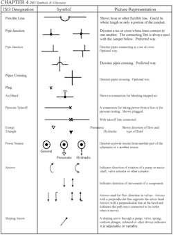
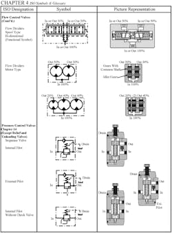
The following pages go through all standard ISO symbol information as it applies to hydraulic and pneumatic schematics. There are still many plants that modify the standards to suit some individual's taste. This widespread practice may be confusing to novices. Symbols have been developed to represent most of the available fluid power components. However, some parts must be made up of combinations of different symbols to show how they function. Other times there is no standard symbol and one must be made up. In such cases, look first in the supplier's catalog for the symbol they show. If the supplier did not make a symbol, the only other option is design one for the new part. Try to design the new symbol using standard practices shown here.
As the phrase fluid power implies, these symbols cover both hydraulic and pneumatic components. Any exceptions are noted.
Read more about hydraulic symbology in a series from author Josh Cosford.