Transverse Flux Motors: A Compact and Efficient Electric Motor Option
Key Highlights
- Transverse flux motors are a type of electric motor which offers the advantage of providing continuous torque over a range of speeds, including low speeds.
- ETM, a division of Graco Inc., has made advancements in manufacturing and copper winding to help make transverse flux motors a more viable option in the market.
- Several applications can benefit from use of transverse flux motors, particularly those with a high duty cycle and continuous loads.
Electric motors are used in a wide range of applications today to drive hydraulic and pneumatic pumps, electric actuators and more.
These motors are typically categorized as radial flux, axial flux and transverse flux, the latter of which is gaining in use due to companies like ETM — the electric motor division of Graco Inc. — advancing the technology in recent years.
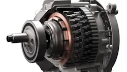
A transverse flux motor, or TFM, is a type of electric motor in which the magnetic flux travels in a transverse, or perpendicular, direction to the axis of rotation of the motor.
Whereas radial flux motors have a magnetic flux that moves radially out from the axis of rotation and axial flux versions have a flux which travels in line with the axis of rotation.
Advantages offered by transverse flux motors include their ability to deliver the highest possible levels of continuous torque in an application, up to 10 times conventional motor technologies, and doing so in a compact, highly efficient package, said Michael Panczyk, Director of Business Development at ETM in an interview with Power & Motion.
In addition, the motor can perform over a broad operating range of speed, while maintaining a high level of efficiency, including lower speeds that can be challenging for traditional technologies.
“It does all of this at the lowest levels of dollars per newton meter of torque,” he said. “What that provides product designers is the ability to get the performance they need at their operating point, rather than having to work around the motor's efficient operating point [which] might be pretty different.”
Because of the advantages it sees in transverse flux motors, ETM has spent years developing the technology and bringing it to various applications and markets.
It’s All in How You Wind It: What Makes the ETM Transverse Flux Motor Different From Conventional Electric Motors
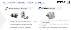
For its transverse flux motor, ETM takes a different approach to creating the magnetic poles used in the motor to make it spin than is typically used in conventional electric motors, enabling the company to achieve a compact and efficient motor design.
Panczyk explained that if your application requires a lot of torque at a lower speed, it typically requires use of a bigger motor, which may not be the most convenient option, or you need to spin the motor faster. But then you have to add a gearbox or belts to gear down to the speed you’re at, adding inefficiencies, design complexity and costs.
The other option is to increase the number of magnetic poles inside the motor. These poles are comprised of copper wire wrapped around steel. “Generally speaking, the more poles, the more torque,” he said.
Adding more poles into the same space claim can be difficult though. And with the additional poles and copper wiring comes increased copper resistance which equates to less efficiency. “It ends up being a losing battle as you try to increase the number of poles,” he said. “The copper resistance just cancels out all your benefits, and you're kind of stuck. And that's the classic dilemma.”
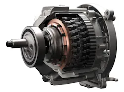
Panczyk said ETM essentially turns the internal architecture of the motor inside out by wrapping steel around the copper to create the magnetic poles instead of using the traditional method of wrapping the copper around the steel.
ETM first creates a donut-shaped or toroidal copper coil that's wound circumferential, he explained. “You're just winding it around, almost like a mandrel. It's kind of like what you would see in a solenoid or transformer.”
Panczyk said this leads to a very simple coil with a lot less copper in it, and thus less copper resistance. Steel is then wrapped around the copper coil.
“Now you have one copper coil instead of [several] individual poles, and you can have as many poles as you want,” he said. “We've now effectively decoupled the electrical circuit from the magnetic circuit, so you can boost the number of poles all you want, and that copper resistance is staying the same.”
All of this translates into a smaller, lighter and more efficient motor, he said.
Panczyk noted there are no special materials used in ETM’s motor. It’s the same copper, magnets and electrical steel you’d find in any other permanent magnet motor, just rearranged in a more efficient way.
Manufacturing processes for the motor are different because of the way the materials are arranged inside of it, but the supply base is the same, which aids costs and production time.
Controlling the motor is the same as other motor designs as well which helps provide familiarity, and thus ease of use, for customers. “There’s going to be some differences in firmware, but basically the same variable speed drives and controls that you use for traditional permanent magnet motors can be used with TFM,” said Panczyk.
Why Now is the Right Time for Transverse Flux Motors
Panczyk said the only thing that has held transverse motor technology back over the years has been the feasibility in manufacturing them.
But ETM has been able to make advancements in the forming and assembly processes, including simplifying the process for wrapping steel around the copper compared to early implementations. “We've simplified that and have made it feasible to do beyond just a lab or university setting,” said Panczyk. “And we can get it so that it runs on high production equipment and can scale up and get more economical.”
The other thing he said that has unlocked the technology in more recent years is the ability to accurately model the magnetic flux that travels through the motor.
Transverse flux motors have a more complicated, three-dimensional (3D) flux path, essentially a spiral shape, compared to radial and axial flux motors which have a simpler 2D flux flow — which has made them easier to develop in finite element analysis (FEA) and other simulation tools.
If you have a 3D flux path, you need 3D simulation capabilities to model how the motor is going to work. “It's only been in the last 10 years or so that the analytical tools have advanced to the point where you can accurately model how a transverse flux motor is going to perform,” said Panczyk. “That development has enabled motor designers to more effectively design the motors than in decades past.
“This coupled with some of the advancements in the intellectual property related to manufacturability and tolerancing have really advanced us to where we are today,” he said.
Watch the below interview with Scott Reynolds, technology commercialization director at ETM from sister publication Machine Design to learn more about the company's development of transverse flux motor technology.
Potential Application Uses for Transverse Flux Motors
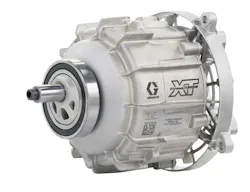
Graco recently chose to employ ETM’s transverse motor technology in its new XT airless paint sprayer because it addressed many of the challenges the company faced with the brushless DC motors it typically used while enabling several performance benefits to be achieved.
Beyond paint sprayers, there are a number of other applications in which the motor can be used as well. Panczyk noted that any pumping, mixing, or blending system that Graco does is a potential fit for the technology.
He went on to say that ETM is also working to license the technology outside of Graco and explore applications outside of fluid management. “Fluid management is a very natural fit, because the real sweet spot of this technology is high continuous torque at high duty cycles,” said Panczyk. “You think of pumps, they are constantly running, the torques are high. That makes a ton of sense [for this motor technology].”
Applications where Panczyk said the transverse flux motor technology could be a good fit include conveyors and other material handling machinery, lifts, hoists, elevators — essentially any application where continuous torque is required.
Replacing pneumatic systems with electric to improve efficiency is another example he offered where the motor could be used. Driving electric actuators is a possibility, he said as long as the duty cycles are high. “If you're constantly cycling an actuator and you're starting to size that motor for heat or you're having to gear it to the level of performance that you need, that's certainly an area we can take a look at for TFM.”
The motor is already being used by some customers to drive the large fans used in many factories, warehouses and other facilities to provide cooling. Panczyk said he also sees potential to use them in the cooling systems employed in data centers to help reduce the amount of energy and water typically required for these systems.
“Our motors are much more efficient at driving these large axial fans [used in data center cooling systems] and could really reduce the energy consumption that's challenging the grid right now,” he said. “It allows for more efficient implementation of dry cooling systems that can also address the water use problems [associated with] data centers.”

Bottom line he said, if an application has a high duty cycle and continuous loads, then the TFM technology is a good fit. “If the load is constant, that's great. If the load is very cyclic, it's going up and down, but it's going up and down fairly quickly and constantly and repetitively, that's a good fit for us.”
Additionally, he said if any of the following factors are true for your application, then TFM could be a good fit:
- a smaller, lighter motor is required
- efficiency is a concern, or
- there is a need to simplify cooling.
Where it doesn’t fit quite as well are those applications in which there are intermittent sporadic loads. “If you're only occasionally actuating something, and then you're resting for a real long time, it’s probably not the best fit for this technology,” he said.
If looking for high speeds, the TFM is probably not a great fit either. Panczyk said it is best suited for lower speeds, around 1,500 rpm or lower. He said ETM continues to advance its motor technology and reach higher speeds, though, which could open up more application opportunities in the future.
About the Author
 Sara Jensen
Sara Jensen
Executive Editor, Power & Motion
Sara Jensen is executive editor of Power & Motion, directing expanded coverage into the modern fluid power space, as well as mechatronic and smart technologies. She has over 15 years of publishing experience. Prior to Power & Motion she spent 11 years with a trade publication for engineers of heavy-duty equipment, the last 3 of which were as the editor and brand lead. Over the course of her time in the B2B industry, Sara has gained an extensive knowledge of various heavy-duty equipment industries — including construction, agriculture, mining and on-road trucks —along with the systems and market trends which impact them such as fluid power and electronic motion control technologies.
You can follow Sara and Power & Motion via the following social media handles:
X (formerly Twitter): @TechnlgyEditor and @PowerMotionTech
LinkedIn: @SaraJensen and @Power&Motion
Facebook: @PowerMotionTech