Fit-for-Life Connections
This file type includes high-resolution graphics and schematics when applicable.

When properly selected, hydraulic flanges reduce the number of adapters used to plumb a hydraulic system. This, in turn, helps shrink system plumbing costs and minimize potential leakage. And their high reliability should make them the least of your worries if there’s a hydraulic system malfunction.
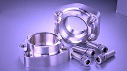
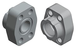
Four-bolt hydraulic flanges have long been a trusted connection for demanding high-pressure mobile and industrial applications. The four-bolt flange design uses a quartet of fasteners to draw two mating flanges together. One flange contains a captive O-ring and the other a smooth machined surface, often referred to as flat-faced. The four fasteners slip through the drilled clearance holes of the O-ring flange and screw into the threaded holes of the flat-faced flange.
When the four fasteners are properly tightened, the O-ring compresses against the flat-faced flange to complete the connection. Such a connection distributes the load across the four fasteners, reducing the likelihood of joint failure due to system vibration. The O-ring or flat-faced flange connections can be manufactured as single- or multi-piece components, where split or captive flanges encapsulate a flange head.
What’s Available?
The most common four-bolt hydraulic flange connections are rectangular patterns conforming to SAE standards J518-1 and J518-2. Other patterns—ISO 6164, CETOP, and JIS—are square bolt patterns less frequently used in hydraulics.
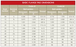
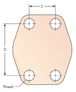
The connections detailed in SAE J518-1 vary in size from ½ to 5 in., with maximum working pressures ranging from 500 to 5000 psi (3.5 to 35 MPa). Typically, pressure ratings decrease with increasing connection size. These four-bolt connections, commonly referred to as Code 61, are also compatible with bolt patterns designed to meet ISO 6162-1.
All of the bolt-pattern connections designed per SAE J518-2 are rated for a maximum working pressure of 6,000 psi (42 MPa). Connections meeting SAE J518-2 range from ½ to 3 in. Commonly referred to as Code 62, they, too, are compatible with a similar ISO standard—ISO 6162-2.
Although an overlap of sizes occurs between J518-1 and J518-2, the products are not interchangeable. Bolt-hole spacing is slightly larger in the SAE J518-2 (Code 62) connections. This difference helps prevent a lower-pressure flange from being installed on a higher-pressure pattern.
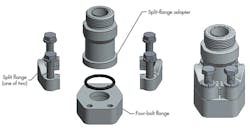
Also available for use with the SAE J518-1 and ISO 6162-1 four-bolt connection is a low-pressure two-bolt flange that’s primarily implemented in suction and return line applications. These unique flanges are designed to be mounted diagonally on existing J518-1 patterns while using the same fastener sizes. Their smaller size reduces material cost, weight, and installation time. Design specifications can be found in SAE J518-3.
Selecting the Right Connections
Typically, flanges have two connections: the flange connection itself and a port connection. The port connection attaches to a hose, pipe or tube. In many cases, a one-piece crimp fitting attaches directly to a hose. However, flanges are also offered in a variety of port connections so that they can be easily adapted to piping or tubing. Socket-weld and butt-weld ends are common for welded connections, while NPT, SAE straight thread, JIC flare, ORFS, and BSPP type threads are helpful when connecting to tubing or other threaded adapters.
Some flanges, called blind or blanking flanges, have no port connection at all, and are used to close off a flange connection altogether. When selecting a flange to adapt to a component, such as a pump, filter, or manifold, use a flange with an O-ring groove, because those components are generally flat-faced. If choosing flanges to bolt together as a pair, such as in the case of a successive piping run, you can select either the O-ring or flat-faced types. Regardless of the flange used, you must consider the pressure rating of the port.
Materials and Finish
Flanges are generally produced in carbon steel and stainless steel, and occasionally in aluminum, alloys, or other exotic metals to meet particular application demands. Since tensile and yield strengths vary between material types, it is important to verify that maximum working pressures are not affected by the material selection.
Though many OEMs paint the entire hydraulic system after fabrication is complete, plating or other finishes can be applied to improve the corrosion resistance and prolong the flange’s life in the field. Carbon-steel components may receive plating such as silver trivalent or zinc-nickel, while stainless steel might be passivated or electro-polished.
Assembly Hardware
Choosing the appropriate hardware, or fastener, is just as important as choosing the right flange. Not only should the type of thread be identified (UNC or metric), but also the proper thread length. Thread engagement is typically provided within the flange specification. However, he flange manufacturer often accounts for it when hardware is supplied as a complete set with the flange. It is common for hex head fasteners to be provided with split-flange connections and socket-head fasteners with four-bolt flanges. In certain applications, special high-strength fasteners can be used because of their ability to resist elongation or stretching, which could result in failure of the flange connection.
Standards continue to be updated, and play a key role in flange selection. In addition, manufacturing and improvements in materials are yielding pressure ratings higher than the industry has ever seen. Big changes are happening in the fluid-power industry, and hydraulic flanges are no exception.
Tim Abrams is Inside Sales Manager and Tom Jones is Technical Sales at Anchor Fluid Power, Cincinnati. For more information, call (866) 352-6437, or visit www.anchorfluidpower.com.
