Clamps retain load if pressure is lost
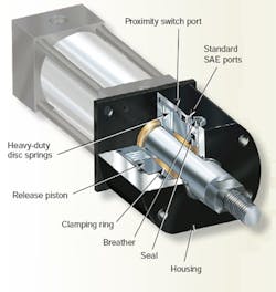
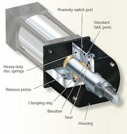
AMLOK series RCH rod lock clamps — developed by Advanced Machine & Engineering Co. — provide power-off holding of hydraulic-cylinder rods after motion has stopped. The clamp’s alloy-steel housing contains a spring-and-collet locking mechanism actuated by a set of disc springs. When hydraulic pressure drives a piston that compresses the disc springs, the locking device releases. Because locking is accomplished mechanically and released by pressure, any loss of pressure automatically causes the unit to lock. RCH clamps are designed to lock reciprocating motion only. (The company also builds special units for both reciprocating and rotary motion, as well as rod lock clamps for pneumatic cylinders.)
The RCH clamps will maintain the rod position securely as long as external forces do not exceed specified values. The holding force depends on the rod diameter and the amount of hydraulic pressure available for unclamping. Clamps are factory preset to release at a specified pressure. A port allows mounting a proximity switch to indicate the unlocked condition. The mountings of the RCH clamp are dimensioned to fit standard heavyduty NFPA-style cylinders. The clamp’s standard housing can attach to any machine structure — or housings can be custom-designed to suit the application.
A few application cautions: when attached to cylinders, longer rods must be specified; the clamp requires a full rod diameter for the entire length of the clamp; and the contact surfaces and bores to which the clamp is mounted must be square and concentric to each other to avoid binding of the rod or causing excess wear. Also, the clamps are designed for zero side loads. If side loads act on the locking mechanism, appropriate bearings should guide the cylinder rod. This is especially important at high stroking speeds to avoid overheating the clamping device due to excessive friction with the rod.
Make contact:
Advanced Machine &
Engineering Co.
Rockford, Ill.
(800) 225-4263
www.ame.com
| Specification ranges for 14 standard models |


