Sensors provide remote monitoring of valve actuators

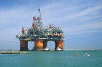
Whether land based or offshore, equipment used in the oil and gas industry involves rigorous, high pressure, dangerous applications requiring high reliability of pneumatic and hydraulic actuators. As oil and gas production systems require increasingly higher pressures and temperatures, companies look for cost-effective ways of remotely monitoring actuator movement. It is no longer acceptable to have to visually inspect actuators in potentially explosive and other hazardous areas. And the ruggedness and non-explosive nature of fluid power technology makes hydraulic and pneumatic actuators the most practical choice for these applications.
Dealing with extremes
Even when valves are not located in hazardous areas, hydraulic and pneumatic valve actuators are still widely used because of their high torque capability, small size, and light weight. When the state of actuators must be monitored only to determine if they are in a completely open or completely closed state, proximity, limit, or other types of switches can be used. But when valve position must be monitored for any point in between, continuous feedback is required.
The challenge is finding a feedback device (position transducer) that can tolerate the wide range of operating parameters typically found in oil field equipment. For example, it’s not unusual to have to monitor valve actuator position when the valve is rated to 17,000 psi and the hydraulic actuator routinely is exposed to temperatures to 300°.
At the other extreme, pneumatic actuators may work near the arctic circle at pressures to 250 psi and test pressures to 450 psi, and may require strokes to 13 in., all in temperatures down to –58°F.
In the past, companies incorporated individual limit switches to indicate open and closed position of valve actuators. This setup required two cables, and setting each switch independently.
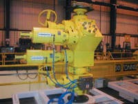
Rota Engineering Ltd., Manchester, U.K., has been working with oil and gas production valve actuator manufacturers to improve high-pressure and extreme temperature actuator control systems. Rota Engineering’s approach incorporates visual, switching, and full stroke linear transducer indication in one complete sealed device with an expected operational life of millions of operations.
The Rota Engineering system requires no setup and only one cable connection. Rota also incorporates the connection back to the platform control system and provides the junction boxes and cabling to enable quick-and-easy installation and removal.
Rota built ATEX, CSA, and IECEX certified explosion-proof, and flame-proof, intrinsically safe, and Increased Safety Zone 1,11 Class 1 Div 11 linear and radial transducers and connector cable systems and provided the engineering and drawing package as a completely built system.
Rota Engineering has supplied the same system to hydraulic and pneumatic actuator manufacturers worldwide, including sub-sea suitable versions. With a stroke of 18½ in., these hydraulic actuators have an internal position transducer and must operate in water depths with static pressure to 10,500 psi.
The Hall-effect alternative
LDTs from Rota Engineering use a microprocessor that transmits and receives signals from Hall-effect chips mounted to a printed circuit board. The circuit board is contained within a stainless steel or aluminum housing, depending on application requirements. A piston-mounted magnet causes a voltage drop when it passes over the Hall-effect chip. The microprocessor calculates the position of the Hall-effect chip and correlates the voltage drop to a proportional voltage, current, PWM, or Canbus output.
Hall-effect sensors generally have resolution of 0.012 to 0.020 in. The tighter resolution of magnetostrictive LDTs is needed for many process applications, such as a rolling mill. However, 0.020 in. resolution is more than sufficient for off-highway equipment, a primary application for the technology.
An additional benefit of the Hall-effect technology is small size. In most instances, the pin-to-pin dimension of a cylinder need not be increased to accommodate a Hall-effect LDT. Also, the surface-mount technology tolerates high levels of vibration, and potting can provide additional vibration resistance.
Submitted by Domhnull McLennan, of Rota Engineering Ltd. For more information, e-mail [email protected], call Rota Engineering in the US at (972) 359-1041, or visit www.rota-eng.com.
