Pressure gauges and flow meters keep an eye on system performance

The majority of gauges for measuring pressure have one common characteristic: pressure being measured is the only source of energy required to provide visual indication of static pressure. Some form of elastic chamber in the gauge case converts pressure to motion, and is translated through links, levers, and gearing into movement of a pointer across an indicating scale. Three types of elastic chambers are used in fluid power system gauges:
- C-shaped, spiral, and helical Bourdon tubes, Figure 1
- bellows, and
- single- and multi-capsule stacks.
Selection
Specifying a pressure gauge involves a number of considerations:
- connection size — nominal size of the port or fitting into which the gauge will be threaded, male or female, and thread size
- mounting configuration — bottom or back-center stem mounted or panel mounted
- dial size — large enough to be seen from a distance but small enough to prevent requiring excess space
- units of measure — determine whether the dial should be calibrated in psi, bar, kPa, etc. Many manufacturers offer gauges with dual-dimensioned scales
- materials of construction — gauges may have a glass or plastic crystal, metal or plastic case, and usually a brass connection. Ensure that materials are compatible with the environment and fluid
- dry or liquid filled — liquid-filled gauges generally contain glycerin to dampen shock and vibration effects, and provide continuous lubrication of the movement to extend life, and
- pressure range — as a rule of thumb, select a gauge with a maximum pressure reading twice that of the anticipated measured pressure. This provides a safety margin to prevent temporary high-pressure pulsations or spikes from damaging the gauge.
Options and accessories
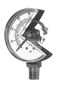
Many options and accessories are available to increase a gauge’s life and operation. Digital readout is accomplished by mounting a strain gauge to the sensing element and using on-board electronics to convert the strain induced by pressure into digital readout on an LED or LCD panel. Digital gauges require a power source — often a long-life battery — and may use a switch so that power is consumed only when a button is pushed to read the pressure.
A gauge isolator, mounted between the gauge and circuit, prevents the gauge from being exposed to fluid pressure unless a button is pushed. Thus, the gauge is not exposed to pressure spikes and pulsations unless they occur when pressure is being read.
Orifices or snubbers protect gauges by smoothing out pressure fluctuations seen by the gauge. Snubbers may cause gauges to respond sluggishly, but can extend life by damping rapid pressure fluctuations. To help protect the gauge from external physical shock, case protectors can be used to encapsulate the gauge in rubber.
Flow meters
Unlike pressure gauges, which have been permanently mounted on most hydraulic and pneumatic systems for decades, flow meters continue to be used primarily to assess the system’s performance. Systems requiring continuous monitoring of flow usually use electronic flow sensors rather than flow meters, which require no power.
Electronic flow sensors use sensing elements (turbines, positive-displacement chambers, differential-pressure measurement, etc.) to generate an electronic signal proportional to or otherwise representative of flow. This signal is routed to an electronic display panel or control circuit. However, flow sensors produce no visual indication of flow by themselves; they need an external power source to transmit a signal to an analog or digital display.
Self-contained flow meters rely on flow dynamics for a visual flow indicator. Although design details differ, flow meters operate on the principle of dynamic pressure. The main components are a tapered shaft and spring-loaded piston.
With no fluid flow, the actuating spring pushes the piston to its left-most position. As fluid enters from the left side, pressure acts against the spring and builds to open the orifice formed between the ID of the piston and OD of the tapered shaft by pushing the piston to the right. As the piston is pushed farther to the right, the orifice area increases because the effective area of the tapered shaft decreases. Eventually, the orifice area will be large enough so that dynamic pressure from flow equals the opposing spring force. The position of the piston in equilibrium, then, provides an indication of flow.
In some applications, flow can be measured directly by comparing piston position to a calibrated scale marked on the flow meter’s transparent outer case. For most hydraulic applications, the piston oftem has an embedded magnet that moves a follower collar; the collar’s position can be compared to a calibrated scale.
Because flow indication depends on fluid dynamics, changes in a fluid’s physical properties can affect readings. This is because a flow meter is calibrated to a fluid having a specific gravity within a range of viscosities. A wide deviation in temperature can change a hydraulic fluid’s specific gravity and viscosity, so if a flow meter is used when fluid is very hot or cold, flow readings may not conform to manufacturers’ specifications. However, most equipment is tested under operating conditions, so readings should fall within manufacturers’ specifications for accuracy.
