Understanding parallel connected valves
In the past few editions of “Motion Control,” two types of open center valves were covered: the full series connection and the partial series connection. In this issue we’ll look at the third and final configuration: the parallel connection. Although referring to those issues to compare details of the three open center valve types would be helpful, here is a brief summary as far as principle characteristics and features are concerned:
Full Series — This configuration makes available the flow from both the upstream bypass and the upstream 4-way return for use in the downstream 4-way functions. It provides for the most complex of interactions between functions that are shifted simultaneously, which are, most notably, flow and pressure intensification and flow regeneration. This amounts to a sort of “recycling” or recovery of the upstream spent flow and can use a smaller pump compared to the parallel configuration, but within the limits imposed by the interactions.
Partial Series — the partial series configuration re-uses only the effluent from the bypass, and as a result, has far less complex interaction between functions that are shifted simultaneously. Regenerative action and intensifications are not possible, but, again, due to flow “recycling,” pump sizes can be reduced relative to the parallel connected open center valve. Simultaneous functions can be activated, however, if an upstream function is fully shifted, then there is total flow cut off to all downstream functions.
Parallel — The parallel-connected, open-center valve stack performs no effluent flow recovery. Instead, all 4-way sections are powered directly from the pump while bypass and 4-way return flow are returned directly to tank. Interaction between simultaneously shifted functions is caused by differences in load pressures, and especially affected by the actions of the transition check valves, and, of course, by the pump capacity relative to load flow demand of more than one actuator.
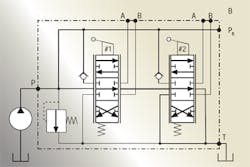
The conventional ISO schematic representation of the parallel configured, open-center, 4-way directional control valve is shown in Figure 1. This and the two previous configurations require transition check valves. They prevent a gravity-loaded cylinder from inadvertently descending when its function is shifted such a small amount that supply pressure has not yet built up enough to hold the load. Previous editions of “Motion Control” further explain these important check valves.
The term “parallel” is derived from the fact that each 4-way spool (function) receives pump flow through a galley in the stack, labelled PB in Figure 1. Thus, all the spools are in parallel. This also means that no recovery of spent flow occurs either through the bypass path or the return flow from shifted upstream 4-way functions. Recall that flow recovery was possible in the full series and partial series and could cause quite complex interactions between loads during simultaneous spool shifts.
Examining interactions
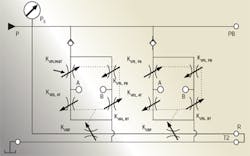
Interactions between functions definitely occur in the parallel configuration. Figure 2 is a simplified analytical schematic showing the active lands when both active 4-way spools are shifted to extend each respective load cylinder. Suppose, for example, that relatively well-balanced loads are on each of two functions to be shifted. If one function is fully shifted while the other is centered, the operated cylinder will extend at a speed determined by its piston area and the pump output flow. If the other function is also shifted, it will “steal” flow from the first function, causing the first function to slow down.
On the other hand, suppose a considerable disparity exists between the loads of two functions, and further suppose that the more heavily loaded function is shifted first by some arbitrary amount. If the lightly loaded function is also shifted, pump pressure will drop because of a lower resistance path in the lightly loaded function. Plus, the heavily loaded cylinder will slow down, and in the extreme case, it will actually stop.
A more complete analytical schematic is shown in Figure 3. This is conventional in that it shows the 4-way sections as bridge circuits with extension and retraction being accomplished by opening two “corner lands” — at the same time sending the opposite corner lands into a greater degree of overlap.
The corner lands act in unison to control flow. That is, KVPL,PA and KVRL,BT are a pair of corner lands that open together. Meanwhile, KVPL,PB and KVRL,AT are the opposite corner land pair, and they will go into greater overlap (shut off) when the other two lands are open. On the other hand, shifting the spool in the opposite direction opens KVPL,BT and KVRL,AT, so KVPL,PA and KVRL,BTgo into overlap. This opposite-going opening and overlap is implied with the opposing arrows over each orifice.
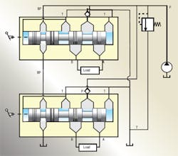
The cutaway diagram for the parallel configured, open-center, 4-way, 2-function, directional control valve is shown in Figure 4. It gives more insight into actual construction strategy but it is a combinational presentation because it shows interconnections simply as lines rather than internal coring and drilling of passages. The nature of the bypass function, however, is easy to visualize in this diagram.
This discussion has shown that the differences in the three open-center valve configurations are subtle in terms of schematic or circuit differences. However, differences in load interactions during spool shifting can be quite different. Also, different kinds of diagrams can help in understanding functions, construction, and characteristics.
Reviewing previous editions of “Motion Control” may give you an appreciation for the various configurations. I have been working with these valves for several years, and I still find it necessary to look back at the details from time to time.
The common thread through the full series, partial series, and parallel valve configurations is the way in which the open-center function is implemented. An integral bypass function requires a special set of spool and body lands to relieve the pump when all the spools are centered. The bypass design is a common practice of designers of opencenter valves. One of the consequences of this method is that the neutral (spools centered) flow has to work its way through all the several spools in the stack. Flow paths may be tortuous due to coring, drilling, and use of subplates. The more spools in the stack, the higher the pressure drop in neutral.
This characteristic is objectionable to the user because it represents totally wasted energy and raises the question, “Is there another way to achieve the relieving function other than threading the flow through the entire stack?” Of course there is. It is the unloader function, which will be discussed next month.
Handbook serves electrohydraulic system designers
The newly published fourth edition of the Designers’ Handbook for Electrohydraulic Servo and Proportional Systems contains even more useful information than its predecessor, the highly successful third edition, which has become the defacto Bible for electrohydraulics technology.
Now you can learn even more about electrohydraulic systems and their design, including:
• how to calculate and control pressure losses in plumbing, subplates, and manifolds,
• how to analyze and control a variety of mechanical loads, including conveyors and belts and triangulated loads,
• valve dynamic properties and how to include them in your system,
• electronics, especially transducers and signal conditioning, and
• mobile equipment electrical systems, including batteries and charging systems.
There is no limit as to how electrohydraulics is going to revolutionize our industry, so order your copy to secure your career in this dynamic technology. And if certification in electrohydraulics is your goal, the fourth edition of the Designers’ Handbook is essential to your preparation. Don’t risk being left behind in a world where the only constant is rapid change.
To order, visit our website at www.hydraulicspneumatics.com, and click on the Bookstore button. Print the PDF order form, fill it out, and mail, fax, or e-mail it to us.


