Crop Sprayer is All About Hydraulics

Experts at Motrac Hydraulics B.V., a distributor and system integrator headquartered in Baak, The Netherlands, recently developed the hydraulic system for a self-propelled agricultural sprayer. The machine requires precise coordination of operations to ensure efficient and consistent application of pesticides or other chemicals despite varying vehicle speed, ground conditions, and routes.
The sprayer has a tank capacity of 4,500 l (corresponding to a load of about 9½ tons) and boom widths from 21 to 40. It is powered by a 218-hp diesel engine and uses a twin-piston diaphragm pump to deliver up to 530 l/min of field chemicals. The engine also drives a hydraulic pump group, consisting of variable-displacement piston pumps and gear pumps.
The drive package uses pendulum tandem chassis with four-wheel drive and independent suspension on all wheels. The chassis, developed specifically for spraying machines, ensures that no motion from the vehicle is transferred to the spray boom. Hydraulics is used for adjustable track width of the wheels and machine height—versatility to accommodate different crops and conditions.
Motrac Hydraulics also designs and installs integrated hydraulic circuits (manifolds and cartridge valves) in-house for all pumps. Depending on the machine, the main pump is generally connected directly to the engine via a mounting flange, with subsequent pumps mounted behind. Motrac often performs this work in-house, furnishing the complete pump line and diesel engine assembly delivered as a unit to the equipment manufacturer’s production line.
This crop sprayer uses hydraulics for propulsion, steering, regenerative braking, and all operating functions.
Open or Closed?
The pumps deliver hydraulic fluid to separate circuits that share a common reservoir. on either open or closed circuits. A hydrostatic drive for propulsion uses a closed circuit, which is more efficient than an open circuit in this application and has fewer valves and greater design freedom. Regenerative braking captures kinetic energy from the moving vehicle and feeds it back to the engine via a one-to-one linkage, which would not be possible with an open system. The closed circuit is also more compact and lighter than an open circuit would’ve been.
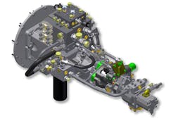
A typical layout for the hydraulic system of a self-propelled field spray unit is shown in the graphic. The first pump downstream of the motor is the ground drive pump, a Linde model HPV model. This pump has a maximum operating pressure of 420 bar and variable displacement adjustable to a maximum of 165 or 210, depending on the machine. A manifold mounted on the pump splits the pump’s discharge flow and routes it to four wheel drives; return fluid is routed to a cooler
The second pump in the line, a Linde HPR 55 or HPR 75 (depending on the machine), delivers constant pressure for all consumers, including steering, track width adjustment, folding out of the boom, etc. Using the constant-pressure pump (which requires pressure at all times) eliminates the need for a priority switching system for steering and allows the use of standard Cetop valves. This is possible because track width adjustment and boom deployment do not occur when the machine is moving, when steering is needed.

A typical layout for the hydraulic system of a self-propelled field spray consists of five pumps mounted front to back off the main hydrostatic pump, which connect directly to a diesel engine.
Next in line is a Linde MPR50 medium-pressure pump, which delivers hydraulic power to drive the spray pump. A special feature of this pump is that it can be adjusted right down to 0 cc at 0 bar—far from common with variable-volume pumps in open circuits. This results in zero energy loss when the pump is not running. There is also no pressure difference between pump pressure and load pressure (load-sense pressure difference is around 25 bar), which conserves energy.
At the end of the pump line are two gear pumps—fixed-displacement, of course. One provides the feed pressure maintain fluid volume in the closed circuit for the ground drive. It also distributes flow to an oil cooler and for pilot pressure to control the MPR 50 pump. The rearmost pump supplies hydraulic power to a fan drive.
All fluid return is combined in a small for subsequent filtering, cooling, and routing to a central reservoir. The manifold can be mounted in an easily accessible location for convenient access to hydraulic lines. The effective oil volume of the system is about 120 l.
Each of the four Linde wheel motors feature simultaneous swiveling of the pump and the drive motor to provide high torque when beginning motion or scaling an incline—causing the system to always operate at maximum efficiency. The system includes an anti-slip system to make a differential unnecessary. A rotational speed sensor fitted to each wheel motor detects when one wheel loses traction. Electronics will then cut power to that wheel, back to zero if necessary. This allows the other motors to transmit more torque. The electronics also ensures close speed control by automatically increasing or decreasing pump displacement as needed.
Material for this article was supplied by Motrac Hydraulics BV, Baak, Netherlands. For more information, visit the company's website.

