Troubleshooting Challenge: Pump-housing Cracking
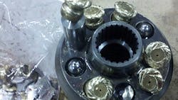
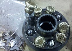
The mill had a problem with the HPU’s main pump breaking into multiple small parts. Personnel determined the problem was caused by the replacement of an inlet hose that had a defective inner liner. As a result, the liner tore loose and tangled into a knot that restricted flow and starved the pump of fluid.
Mechanics replaced the pump and changed the pressure-line filter elements. They also drained the oil, cleaned the tank, and installed new, filtered oil. The HPU was designed so the pump had a flooded intake line. They filled the pump case with new oil and started the system.
After initial pump noise settled down, and the pump compensated at 2,800 psi, they opened the ball valve to a 10-gal accumulator. When the pump compensated after filling the accumulator to 2,800 psi, the pump’s shaft seal failed, and the pump housing cracked—both at the same moment.
Any idea what caused the problem?
Find the solution
Think you know the answer to this month’s problem?
Submit your solution by emailing Mindy Timmer at [email protected]. All correct solutions submitted by March 3, 2015, will be entered into a random drawing for a $50 gift card. The winner will be notified, and his or her name will be printed in a future issue. Only one gift card will be awarded to any participant within a calendar year.
Congratulations to Ken Westin, of Hahn Machinery, Two Harbors, Minn., who won December’s Troubleshooting Challenge by having his answer drawn at random from those who correctly solved that month’s problem. A $50 gift card was sent to him.
Solution to December’s problem: Speed control causing unwanted jolt and pressure spike
The item that caused additional concern was the 4,000-psi rod pressure. A 5-in. bore cylinder with a 3½-in. rod has an area ratio of approximately 2:1. All meter-out flow controls located on the rod side will cause intensification directly related to the area ratios and the force the load exerts on the rod. Remember the old quote, “When in doubt, meter out.” But I always add, “But watch out,” to remind us of this potential problem.
As far as the actual cause of the bump that occurred when shifting speeds: when a two-position directional valve shifts, it moves through a transitional position before reaching its final position. Most two-position directional valves have a blocked center during transition, which was the cause of this problem. The shifting valve momentarily blocked flow, then opened to the flow control. This caused the bumping problem.
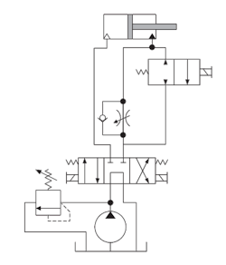
This problem has a couple of good solutions. One is to use a directional valve with a transitional center open to both ports. Another would require re-plumbing to parallel the flow control around the two-position directional valve, as shown in the revised circuit. This is what we recommended, and it solved the bump problem. Flow would pass through both valves for high speed and drop to the slower speed when the directional valve was shifted.
Pressure intensification is inherent in meter-out circuits. The cylinder, flow-control circuit, and piping must all be rated for the 4,000-psi pressure. However, using a meter-in circuit and adding a counterbalance valve to the rod side would also eliminate the intensification problem.
About the Author
Robert Sheaf
President
Robert J. Sheaf Jr., is the founder and president of CFC Industrial Training, formerly Certified Fluid Consultants, part of CFC-Solar Inc. CFC-Solar provides technical training, consulting, and field services to any industry using fluid power technology.

Leaders relevant to this article:


