Exploring an alternative pump control method
Using a variable displacement, servo-stroked pump can significantly reduce power otherwise wasted by systems using valve control. Valves perform their control either by giving up power when required by the load, or absorbing the excess pump output power when the load does not need it.
The biggest challenge to using pumps to control cylinder motion is accommodating a cylinder's different rod and cap end flows. A method will be presented using pump control, and it will also accommodate the differential area problem with single rod end cylinders. However, first we will examine the more obvious solution — a conventional hydrostatic transmission controlling a double rod-end, equal area cylinder.
Make it a double
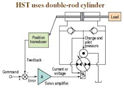
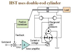
A prototype system is illustrated below: a typical hydrostatic transmission (HST) pump powering a symmetrical area cylinder (rather than the conventional hydraulic motor). A charge pump ensures that pump internal leakage is made up through the check valves. At the same time, this prevents the lower pressure of the two HST power lines from dropping below the charge pressure.
The system is also an example of a closed-loop control system, so we must make a distinction between closed loop — which often is applied to the hydraulic power circuit of Figure 1 — and closed circuit, which is sometimes used to identify the same thing. In this discussion, closed circuit refers to the HST pump and cylinder wherein the flow out of the return end of the cylinder is consumed by the pump without first going through a reservoir. Closed loop will refer to the feedback control system, which in this case, is a position control loop.
Closed-loop control
Here's how it works: The pump's servo stroke controller is set up so that a 0-V or 0-A signal from the servo amplifier will cause the pump to go to neutral, or zero stroke (zero swashplate angle). Of course, the error is the difference between the command signal and the feedback signal. Therefore, the error is zero, the servo amplifier output is zero, the pump swashplate angle is zero, and we expect the cylinder will not be moving. It further follows that the command and feedback signals must be equal when the error is zero.
Now, if the command signal increases, the error will be non-zero and positive, and the current or voltage signal from the servo amplifier will cause the pump stroke to also become non-zero. The cam angle increases, flow from the pump increases, the HST differential pressure increases, and the piston and load move. If the servo loop is phased correctly, the flow will be in a direction that causes the cylinder to move in a direction that will, in turn, cause the feedback signal from the position transducer to increase.
So, as the cylinder extends, eventually, the increasing feedback voltage will equal the new command voltage. The error and current or voltage signals will go to zero, and the pump stroke will go to neutral. The HST differential pressure will go to zero (or nearly so), and the cylinder will stop at a new position, commensurate with the new command voltage.
Thus, we have a closed loop, positional servo mechanism in which the position of the cylinder will correspond to the value of the command signal. The cylinder and load can be commanded to move to a desired position either through a manual input or from automatic motion-control profile inputs from a motion controller.
Benefits of pump control
Although I have no first-hand experience with such a servo loop, undoubtedly it has been successfully implemented. The main advantage is the energy savings that comes from using pump control rather than valve control. No energy loss occurs as fluid is forced to pass through small valve metering lands at high pressure. Moreover, the system is capable of power regeneration. Regeneration occurs when power is directed to the cylinder to accelerate the load. However, upon deceleration, the decreasing pump displacement causes the HST differential pressure to reverse sign as kinetic energy is removed from the load. Also, the cylinder becomes a pump, converting mechanical power into hydraulic power that transforms the HST pump into a motor, which over-drives the prime mover. If the prime mover is an induction motor, the induction motor transmits electrical energy back onto the electrical power grid to be used by other electrical consumers.
Energy-saving operation is an obvious and important advantage of this system. However, there are disadvantages. The most obvious is the use of a double-rod end cylinder. When the cylinder stops, the pump is in neutral, and if there is no load on the cylinder, then the two cylinder pressures will be very nearly equal to the charge pump pressure — no more than a few hundred psi. This will result in a lack of stiffness, relative to the valve-controlled system, wherein both cylinder ports are always at elevated pressures, even without load. Loop stiffness is needed to maintain a commanded position in the face of changing loads. Under any steady-state condition, one HST power line will always be at charge pump pressure.
Also, it is often difficult making clearances for the unused rod to move into and out of the cylinder. It has to move in an area where people and equipment will not be impaled by it.
Though not particularly a disadvantage, the servostroked pump is actually serving as a servovalve. The pump has to be tested for some of the same parameters that routinely are measured in servovalves. The most important ones are the pressure gain, hysteresis, and frequency response. Pressure gain and hysteresis directly affect the ability to accurately acquire and hold a commanded position. It is conceivable that in the neutral position, pump internal parts are more or less floating in the absence of significant pressure, and both flow and pressure metering could suffer. Again, these issues can directly affect the ability to acquire and hold position.
More will be said about frequency response in a subsequent edition of "Motion Control." We have now laid the groundwork for examining a pump controlled cylinder that will overcome some of the problems just described, which will be introduced next month.


