A simple solution for a high-tech application
Experts at Oak Ridge National Laboratory call on hydraulics for an important function of controlling the flow of neutrons in the Spallation Neutron Source (SNS). The SNS is currently used for advanced R&D and materials development in such varied markets as semiconductors, medicine, and materials engineering. It will be the most intense and powerful pulsed neutron beam source in the world when it achieves full power of 1.4 MW. The flow of electrons is regulated in a neutron delivery system by positioning a series of shutters, and the position of each shutter is controlled by a hydraulic cylinder.
The neutron delivery system consists of 18 30- and 50-ton shutters, raised and lowered 20 and 30 in., respectively, by stainless steel hydraulic cylinders. The cylinders operate at pressures to 2200 psi using tap water that is continuously filtered and sterilized. The shutters are lowered by gravity, so downward motion can easily be controlled through a simple and reliable meter-out circuit. Raising and lowering can occur four times every hour, for approximately 5000 hr of annual use.
Safety catches on
As ORNL engineer Ken Chipley explains, "We investigated a number of solutions to solve the shutter operation challenge, working with Dave Vesco and his team at TPG Applied Technology in Knoxville, a company that specializes in the engineering of remote operation and robotic systems used in radioactive and other hazardous areas. After reviewing several options for the shutter operation integrity, we decided on safety catchers for the drive rods."
Each shutter drive cylinder is equipped with two Sitema Safety Catchers, supplied by Advanced Machine & Engineering Co. (AME), Rockford, Ill. Typically, Sitema Safety Catchers protect equipment and personnel on hydraulic and pneumatic presses, as well as on material-handling equipment, molding machines, automotive assembly transfer lines, people movers, and amusement park rides. In this application, the safety catchers were needed to prevent gravity from lowering the shutters, in the event of hydraulic pressure loss, cylinder failure, control valve failure, or other system malfunctions.
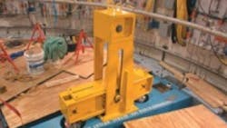
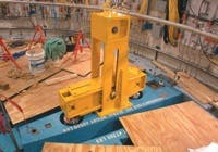
A pair of custom designed hydraulic release stainless steel safety catchers is used on each of the shutters. Parallel piston rods are connected mechanically by a bridge cross-beam mechanism, also manufactured by AME for this application. In the up (closed) position, the shutter is suspended by the piston rods.
The safety catchers release when fluid pressure reaches 2200 psi. The fluid is routed to the cylinders through stainless steel hydraulic tubing, controlled by a central pump and flow controls. Spring-loaded bases and proximity switches, which monitor the release and catch positions, are also part of the catchers.
The safety catchers are recessed within solid steel shield blocks, so all hydraulic porting was designed for topside access to enable easier installation and maintenance. Seals and elastomeric materials used on these safety catchers needed to be suitable for radiation exposure. All functionality test results and materials certifications were supplied to the strict requirements of ORNL.
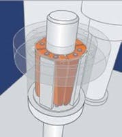
Describing the operation of the safety catchers, Ken Davis, AME's Fluid Power Division Business Development Manager, explains, "Sitema Safety Catchers develop holding force on the rod by self-intensification, created by the load as the rod is traveling downward. Therefore, release pressure is needed to move the rod downward. Sitema Safety Catchers do not develop holding force, with or without release pressure, when the rod (load) is traveling upward. Proximity switches are used to monitor the catch or release function of the safety catcher. The spring base compensates for radial and angular misalignment."
If the load should begin to drop without hydraulic release pressure, the self-intensifying blocking mechanism in the safety catcher engages the load and secures it until the load direction is reversed and the pressure is restored. Simply restoring the release pressure will not release the load, Davis notes.
Water is used for this hydraulic system because it is inert and not susceptible to radiation damage, nor does it pose a flammability hazard. The tap water used here is constantly filtered and sterilized, as it runs through sanitary-grade, Schedule 80 and stainless steel piping. Separate hydraulic control manifolds are used so that each instrument operates independently. Likewise, each lift cylinder has its own leak detection system.
For more information, contact Ken Davis, Advanced Machine & Engineering, at (815) 316-5247, [email protected] or Ken Chipley, engineer, Oak Ridge National Laboratory, at (865) 574-6411, [email protected]


