Hydraulic Diagrams You Should Not Do Without
A picture is worth a thousands words. And so is an accurate hydraulic diagram. It can also be worth a lot of nickel. Consider the four main types of hydraulic diagrams in common use -- and the consequences of having to manage without them:
Block Diagrams show the components of a hydraulic circuit as blocks joined by lines, which indicate connections and/or interactions.
Cutaway Diagrams show the internal construction of hydraulic components and their flow paths. Because these diagrams typically use colors, shades or patterns in the lines and passages, they are very effective at illustrating different flow and pressure conditions.
Pictorial Diagrams show a hydraulic circuit's components and piping arrangement. The hydraulic components are seen externally and are usually in a close reproduction of their actual shapes in scaled sizes. This aids in hydraulic component recognition and identification.
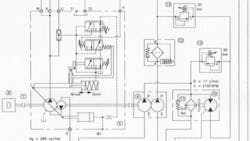
Graphical Diagrams are the shorthand system of the fluid power hydraulics industry. They comprise simple, geometric symbols, drawn to ANSI or ISO standards that represent the hydraulic components, their controls and connections.
To a hydraulic technician skilled in reading and interpreting them, a graphical circuit diagram or schematic is a valuable aid in identifying possible causes of a problem. And this can save a lot of time and money in a hydraulic troubleshooting situation.
If a hydraulic schematic diagram is not available, the technician must manually trace the actual, physical circuit and identify its components in order to isolate possible causes of the problem. This can be a time-consuming process, depending on the complexity of the hydraulic system.
Worse still, if the hydraulic circuit contains a valve manifold, the manifold may have to be removed and dismantled - just to establish what it's supposed to do. Because if the function of a component within a hydraulic system is not known, it can be difficult to discount it as a possible cause of the problem.Schematic diagrams eliminate the need to reverse engineer the hydraulic system.
A picture may be worth a thousand words, but THIS one can be worth a thousand dollars (or more!). In other words, not keeping track of your hydraulic drawings or failing to keep them up to date can be a costly mistake. And to discover six other costly mistakes you want to be sure to avoid with your hydraulic equipment, get "Six Costly Mistakes Most Hydraulics Users Make... And How You Can Avoid Them!" available for FREE download here.
About the Author
Brendan Casey Blog
Author
Brendan Casey is a war-weary and battle-scarred veteran of the hydraulics industry. He's the author of The Hydraulic Troubleshooting Handbook, Insider Secrets to Hydraulics, Preventing Hydraulic Failures, The Definitive Guide to Hydraulic Troubleshooting, The Hydraulic Breakdown Prevention Blueprint and co-author of Hydraulics Made Easy and Advanced Hydraulic Control. And when he's not writing about hydraulics or teaching it, Brendan is flat-out helping consulting clients from a diverse range of industries solve their hydraulic problems. To contact him visit his company's Website:
www.HydraulicSupermarket.com
