Hydraulic-Electric Analogies, Part 5: Current and Electrical Fields
Electrical engineers take pride in the precision of their language, despite contradictions such as in the case of open and closed switches. Specifically, when applying an open circuit to a switch, it can’t conduct — the anomaly is caused when projecting an open-circuit condition onto a switch condition. Contrarily, an open valve conducts fluid while a closed valve does the opposite (a more intuitive use of open/closed terms).
However, all isn’t perfect in EE-speak. For instance, another important contradiction in electrical circuit and system language revolves around the issue of “electron current” versus “conventional current.”
The motion of loosely bound electrons in conductors, motivated by the electrostatic field therein, creates electrical current. Extensive studies on nuclear physics reveal that the electron, with its negative charge, is the mobile charge carrier in all circuits. Even armed with that knowledge, though, the electrical-engineering profession prefers to cling to the notion that the mobile charge carrier is some fictitious positively charged particle! How is that possible? Seemingly, history is the trigger for this line of thought.
Keeping with tradition
James Clerk Maxwell’s [1873] seminal equations, which describe the relationships between electrostatic and magnetic fields, explain how light and radio waves propagate through space and time. However, they were written well before the atom was visualized in its current form; that is, as a nucleus of positive charges (protons) being orbited by the mobile negative charges (electrons). This model was formulated by Niels Bohr in 1913 — some 40 years after Maxwell.
In the meantime, the work of Maxwell and others in the intervening years all assumed a positive charge carrier. Subsequently, a bunch of “right-hand rules” were put forth. To preserve the early work and maintain the rules, electrical engineers hold forth with the concept of a mobile positive charge carrier, knowing full well that it’s literally incorrect. Thus, conventional current theory persists to present time.
Today, very little use is made of electron flow, except in certain government training programs. It’s important to understand, though, that it really doesn’t make any difference in the end. Circuits can be analyzed with either theory, provided that all rules are reversed when using electron current, and you don’t change protocols mid-problem.
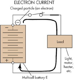
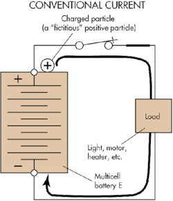
Figures 1 and 2 show the electron/conventional current ideas. The electron moves out of the negative terminal of the battery (voltage source) while the conventional current’s fictitious particle (there is no name for it, it’s just there) leaves the battery’s positive terminal and returns through the negative terminal. In the following discussion, conventional current rules and notation will be followed, consistent with my educational roots.
A primer on magnetism
In terms of current for electrohydraulics, magnets and magnetic fields play important roles. Magnets occur in nature as lodestones, which are permanently magnetized pieces of magnetite. They fall into one of two broad categories: permanent and electromagnets. Magnets can contain iron, cobalt, or nickel, and some rare-earth minerals. These ferromagnetic materials are also attracted to other magnets.
Magnetism is characterized with a magnetic field caused by an electrical current and the field that permeates the region surrounding the current-carrying conductor. This characteristic, which occurs because of moving electrical charges, has no analogy in hydraulic circuits.
The subtle current in permanent magnets is due to certain materials — such as those already noted — containing atoms that are “all lined up.” In other words, the iron atoms in a nonmagnetized core are randomly aligned, and the magnetic field of the orbiting electrons of one atom is cancelled by that of its neighbors. However, if those orbiting atoms can be aligned to spin in the same direction, it results in a magnet whose source is within the material itself.
When immersing a ferromagnetic material of the right properties in some external magnetic field, and then removing the external field, enough of the atoms remain in orbital alignment so that permanency of the magnetism imparts to the core material. In fact, this is how permanent magnets are created. Lodestones are magnetized from being immersed in the earth’s magnetic field for eons.
Electromagnets have temporary magnetism, but aren’t called temporary magnets. Their magnetism comes strictly as a result of currents carried by an accompanying conductor. When the current is taken away, the magnetism goes away, too.
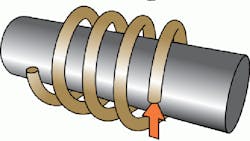
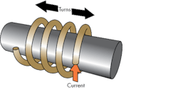
An electrical coil helps enhance magnetic-field strength — the field created by one turn of the coil is reinforced with the field of the adjacent coils as flux lines. Further enhancement is possible by wrapping the coil around a ferromagnetic core, similar to the simple arrangement in Figure 3. The electromagnet exhibits the same characteristics as the permanent magnet, other than the ability to turn off the magnetic field.
The figure is simplified because a practical electromagnet would have tens, if not hundreds, of turns, often with layered turns. That is, later turns are wrapped directly on top of earlier ones. All of the turns contribute to the magnetic field. Adding a ferromagnetic core increases magnetic-field strength by hundreds of times more than an air-core coil at the same current and number of turns.
Solenoids — the most common electrohydraulic application (along with, to some extent, torque motors) — all have ferromagnetic cores. The value of the electromagnet, in addition to on and off capability, is the generation of an on/off force that attracts other ferromagnetic material.
Magnetic force in a state of flux
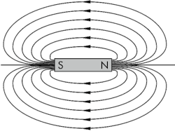
Understanding magnetic force is aided by the invention of the north and south magnetic poles and magnetic-flux field surrounding the magnet. Figure 4 shows a simple bar magnet that’s linked to flux lines. Flux exists around both permanent magnets and electromagnets. Lines of magnetic flux originate in the magnet and close on themselves, so that each one forms a complete loop.
The number of flux lines surrounding the magnet determines magnetic-field strength, and the closeness of the flux lines to one another indicates “flux density.” Thus, flux density is greatest right at the magnet’s pole. Flux is also given a direction, though it doesn’t constitute motion like the moving charges in a current. The direction is assigned as emanating from the north magnetic pole and reentering the magnet at its south magnetic pole.
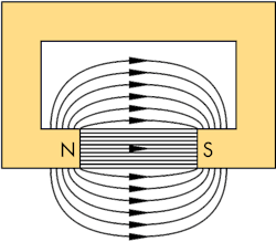
Magnets can be shaped in various ways to enhance the amount of flux. Flux density affects the amount of force that can be obtained from the magnet; therefore, geometry that increases flux density is desirable.
Figure 5 shows a basic example of geometric effect used in electric motors and generators. Forming the core in the shape of a horseshoe and making salient pole faces that are opposite one another greatly enhances the flux density in the air gap (the region between the pole faces). In addition, the closer the pole faces are to one another, the greater the flux density. Any nonmagnetic material put between the pole faces inhibits the amount of flux and reduces the magnet’s effectiveness. The most common nonmagnetic impediment is just plain air, which is why the unoccupied space is called the “air gap.”
Hysteresis
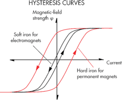
Hysteresis is a naturally occurring phenomenon in both electrical and mechanical materials and devices. It occurs in input-output devices such as magnets, whereby the curve traced while increasing the input doesn’t track over the curve while decreasing the input.
Figure 6 shows hysteresis curves for two different ferromagnetic materials that comprise the cores of two electromagnets. The magnets are, nominally, constructed simplistically like that shown in Figure 3. When the core material is soft iron, the increasing and decreasing curves stay closer to one another. With hard iron, constructed with certain alloys, the hysteresis curve has a much wider opening.
Permanent magnets typically use hard-iron alloys because they retain their magnetic fields even after removing the motivating source (the current). To make a permanent magnet, the hard-iron alloy is immersed into the center of an electrical coil. Current is then increased through the coil to some predetermined level, at which point the current is shut off. The end result is permanently magnetized hard-iron alloy.
For electromagnets, soft iron is the best option. The iron gives up its flux once current is removed and, thus, gives up its force as well.
Magnetic saturation, also shown in Figure 6, occurs because the ferromagnetic core can’t build any more flux with increasing current. Naturally occurring like hysteresis, it limits the physical sizes of electromagnetically motivated machines (motors, generators, solenoids, etc.). To get more flux, which creates more force, the magnets must be made larger. Larger currents work to increase flux only up to the saturation point, though.
To further boost flux, new magnetic materials were developed toward the end of the last century using so-called rare-earth elements. Two that have flourished are samarium-cobalt and neodymium magnets. They can double the flux density over more conventional iron cores. Future discoveries in magnetic materials could eventually lead to electrical machines that produce as much power per pound as hydraulic machines.
Hysteresis in magnetic materials does serve a role in terms of memory. Interrogation of the magnetic-field direction (positive or negative) will reveal what was last done to the magnet. In other words, the magnetic material “remembers” the polarity of its last input current or magnetic pulse. If positive, it’s called a logical 1, and if negative, it’s called a logical 0. Of course, 1s and 0s comprise the language beloved by digital machines.
An extension of this idea comes as the ferromagnetic coating found on the surface of hard drives. The coating consists of individual, microscopic magnetic domains, each one a storage place for 1s and 0s. The domains are so tiny that trillions can be stored on a disk drive hardly larger than a deck of playing cards, all of it based on ferromagnetic magnetism and hysteresis.
Two common types of hysteresis exist. The first is in the form of mechanical backlash — such as between a pair of poorly meshed gears — but also in other mechanical linkages that are either loosely connected or become loose through mechanical wear. The output curve for input motion in one direction doesn’t trace over the output curve for the opposite direction of input motion. The second instance is when hysteresis occurs due to stiction, or stick-slip friction. Again, output doesn’t track when comparing opposite directions of input motion. Servovalves, for example, exhibit hysteresis because of electromagnetic phenomena as well as frictional effects.
Mechanical voltage generation
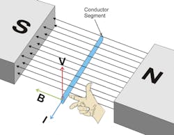
Magnets aren’t used solely to create controllable forces. They also generate voltage. According to Lenz’s Law, any time an electrical conductor “cuts through” flux lines, a voltage is induced in the conductor. Furthermore, Lenz taught us that the flux created from any induced-voltage current will be in a direction opposite to the flux that created it. It’s important to remember that a voltage can be induced due to the relative speed between the conductor and the magnetic field.
Figure 7 illustrates the idea and how the right hand rule applies. Two magnetic pole pieces are labeled N and S, representing the north and south poles of some magnet. A magnetic flux field is labeled B (flux density), and points from the north pole to the south pole. Immersed in about the middle of the flux field is a conductor segment, which is moving upward with a velocity of V. In order to move upward, the conductor must pass through the field. Thus, it is said to “cut” the lines of flux, a criterion for inducing a voltage. Because of the right-hand rule (thumb points in the direction of V and the index finger points in the direction of the magnetic field, B. Therefore, the charged particles will move in the direction indicated by the middle finger.
The current direction is generally perpendicular, coming out of the page. The charged particles that constitute the current are those fictitious positive mobile charge carriers introduced earlier. The I arrow points in the direction of conventional current.
Generators and alternators of construction variations that are too numerous to mention are built around Lenz’s law. By putting a multiplicity of turns on a coil and spinning that coil in a magnetic field, large and powerful generating machines can be built, and they are. They all work on the same principle.
