CHAPTER 10: Directional Control Valves, part 2
Poppet-type pre-fill valves
Pre-fill valves operate similarly to pilot-operated check valves, but they are usually much larger. Some pre-fill valves can handle flows in excess of 6000 gpm at pressure drops of less than 4 to 8 psi. Their normal function is to fill and exhaust a large bore cylinder as it travels to and from contact with the work piece. Large, high-tonnage presses -- both vertical and horizontal -- use pre-fill valves to reduce pump size while maintaining cycle time.
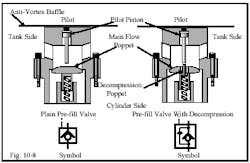
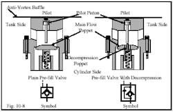
The cutaway view and symbol in Figure 10-8 show the construction of a typical poppet-type pre-fill valve. A large main-flow poppet seals the path between the tank and the cylinder ports. As the piston advances, vacuum in the void behind it allows atmospheric pressure to push the main-flow poppet open so fluid from the tank can fill this void. On the retraction stroke, a signal to the pilot piston pushes the main-flow poppet open so fluid can return to tank. While a pilot-operated check valve’s pilot piston is larger than the poppet it opens, the main-flow poppet in a pre-fill is much larger in diameter than the pilot piston. Thus it is impossible to open the main-flow poppet against high backpressure. This keeps decompression shock from damaging pipes and components.
Decompression shock occurs when large volumes of fluid at high pressure are released suddenly. Because all hydraulic oil has some entrained air (bubbles so small they cannot be seen without magnification), there is a 0.5 to 1% compressibility that must be dealt with when using large-bore cylinders. On top of fluid compressibility, the cylinder tube may stretch diametrically and longitudinally. In addition, the framework that is resisting the tonnage produced also can stretch. Summing all these factors, a 50-in. bore cylinder with a 72-in. stroke can contain more than 25 gal of extra fluid at 3000 psi. If this trapped fluid suddenly has a large open path to atmosphere, its velocity at first release is such that it can break fittings, blow hoses, straighten tubes or pipe bends with relative ease. Releasing this same trapped fluid in a controlled manner over a few seconds dissipates the excess energy and no damage is seen.
The plain pre-fill valve might be used on smaller cylinders or circuits that have other means for decompressing. The pre-fill valve with decompression has a small poppet in the large poppet that is easy to open at high pressure but will not allow the high flow that causes decompression shock. This decompression poppet usually has a means to adjust how fast the cylinder decompresses.
Another pre-fill valve design is the sleeve type that must be externally shifted open and closed. Both designs give the same results even though their operation is different. (See Chapter 4 for a cutaway view and symbol of a sleeve type pre-fill valve.)
Typical decompression circuit
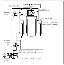
The circuit in Figure 10-9 operates a vertical single-acting hydraulic ram press with pullback cylinders for the retraction stroke. The press has a poppet-type pre-fill and gets a fast stroke from only filling the pullback cylinders during the approach stroke. A sequence valve keeps pump flow from going to the ram until pressure reaches a preset level.
During the approach part of the stroke, atmospheric pressure pushes fluid into the large-bore ram through the pre-fill valve because there is vacuum behind the extending ram. When it contacts the work, the ram stops and the pre-fill valve closes. Pressure starts to rise and when it is high enough to open the sequence valve, pump flow goes to the pullback cylinders and the ram. Extension speed slows and tonnage increases to do the work required.
A signal that the work is complete shifts the directional control valve to send pump flow to the rod ends of the pullback cylinders and to the pilot signal of the pre-fill valve. The pre-fill valve’s pilot piston moves forward and contacts the decompression poppet. This lets trapped fluid flow out at a controlled rate. Pressure in the ram drops quickly and smoothly. When pressure is low enough, the pilot piston opens the main poppet to let fluid from the ram return to tank. When the ram loses pressure, the pullback cylinders can raise the platen and push fluid from the ram back to tank.
General directional control valve terminology
Directional control valves are specified generally by the number of ports or ways (lines attached to the symbol’s box) and the number of positions (boxes or envelopes in the symbol) they have. Other information about them includes whether they are normally closed (not passing fluid), normally open (passing fluid), how they are operated (solenoid, manual, or spring) and other features such as manual overrides, drain ports, pilot ports, etc.
Some general rules for drawing symbols are:
- only draw flow lines to one box of the symbol
- always see that flow paths and direction of flow in each box is compatible
- on 4-way hydraulic valves, pipe the A port to the cap end of the cylinder and the B port to the rod end
- draw all symbols in their at-rest position. Show valves that are held actuated by a machine member in their shifted condition, and
- provide information such as pressure settings, flow rates, orifice sizes, horsepower and rpm where applicable.
(According to this method of specifying, check valves and pre-fill valves would be 2-way valves because they have two ports. However, because these valves are basically single function and have infinitely variable flow paths, their symbols and terminology do not follow general directional control valve rules.)
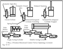
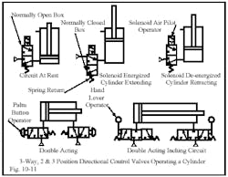
Figure 10-10 shows the symbol for a 2-way directional control valve and how it could function in a circuit. Notice the symbol has two boxes (or envelopes) to indicate two positions. Each position is a flow path. The box with flow lines coming to it is the normal or at-rest position of the valve. The normal or at-rest position is usually at the spring end of a spring-return valve as seen in the figure.
The circuit at rest in Figure 10-10 illustrates how a schematic drawing shows the component symbols for the system builder or troubleshooter. Valves, actuators, flow paths and line connections are all shown according to the ANSI or ISO graphic symbols that were explained in Chapter 4. To understand how the circuit operates, a person must be able to read the symbols and know how they represent a piece of hardware. The valve in this circuit is 2-way, 2-position, direct solenoid-operated, spring return, normally closed. The diagrams to the right of the circuit at rest show how the directional control valve shifts to its second position and ports fluid to the cylinder. In the real world, this is done in a person’s imagination . . . and can be confusing when several valves are working simultaneously. In the diagram it is easy to see that with the solenoid energized, the normally open box moves in line with the input flow and sends fluid to the cylinder. The arrow in the normally open box shows flow from inlet to cylinder port, causing the piston to extend. If the solenoid is de-energized, the spring returns the valve to the circuit at rest condition and the cylinder stops in its last position.
Two-way valves cannot have more than two positions because they can only stop or allow fluid flow. It is easy to see that a 2-way directional control valve will not operate a single-acting cylinder. These valves are only good for operations that require an on-off supply. As shown in the bottom half of Figure 10-10, two 2-way valves are needed to control a single-acting cylinder. A double-acting cylinder needs four 2-way valves to control it. There are both normally closed and normally open valves in these circuits.
Figure 10-11 shows how 3-way valves can replace 2-way valves and make a machine simpler. This circuit at rest has a cylinder powered by a 3-way, 2-position, solenoid pilot-operated, spring-return, normally closed directional control valve. Because this valve has a flow path from the pressure port to the cylinder port and from the cylinder port to atmosphere, it can control a single-acting cylinder. The diagrams to the right show that when the solenoid is energized, the cylinder extends under power. The next schematic diagram shows the cylinder retracting from external forces with the solenoid de-energized.
Two 3-way valves are needed to power a double-acting cylinder as shown in Figure 10-11. The double-acting palm button activates this circuit. The valve on the cap end is normally closed and the valve on the head end is normally open. This is a simple anti-tie down circuit, but is not OSHA safe because one palm button can be depressed before the second one and the cylinder will move. OSHA requires that both buttons be operated concurrently to make the cylinder extend. It does meet the anti-tie down requirement because the cylinder will not retract until both palm buttons are released.
The double-acting inching circuit in Figure 10-11 uses two 3-way, 3-position, spring-centered valves to make it possible to stop the cylinder at any point in its stroke. A 3-way valve can have a third position to perform another function. The pictured center condition has all ports blocked, which stops flow at all ports. This is the center condition normally found on a 3-way valve.
Note: pneumatic inching circuits cannot stop and hold a load consistently. Any change in speed, load, or pressure can produce a different stopping position. About plus or minus one inch would be the best position accuracy an air cylinder would achieve, unless it is moving very slowly. Air leaks in the plumbing or valves also interfere with trying to stop and hold an intermediate position. Leaks may let one end of the cylinder bleed off and allow air from the opposite end to expand and move the cylinder out of position.
Continued
Using two 3-way valves attached directly to each cylinder port will save air. By eliminating all piping between the valve and the actuator, less air is consumed during each cycle. The air savings per cycle may not be great, but it can add up on fast-cycling equipment with multiple cylinders.
A 3-way valve can be used as a 2-way function when an on-off condition is needed.
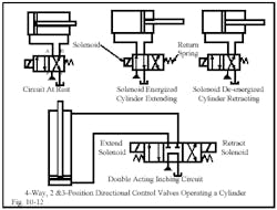
The 4-way valve in Figure 10-12 makes it possible to operate a double-acting cylinder with a single valve. The four ports on hydraulic valves are marked P for pump, T for tank, and A and B for cylinder or outlet ports. Most valve manufacturers follow this universal marking system. Most air valves are configured as 5-way functions with two exhaust ports. This works well for air valves because atmosphere is the tank. Return piping is not required.
The circuit at rest in Figure 10-12 shows a 4-way, 2-position, direct solenoid-operated, spring-return directional control valve. In at-rest condition, pump flow holds the cylinder in the retracted position while the cap end is ported to tank.
In the solenoid-energized, cylinder-extending condition, pump flow connects to the cylinder cap end while the head end is connected to tank. The cylinder is extending under power at this time. In the solenoid-de-energized, cylinder-retracting condition, the valve returns to normal and the cylinder retracts under power.
A single 4-way directional control valve can power an actuator in both directions. At the bottom of Figure 10-12, a 4-way, 3-position, double direct solenoid-operated, spring-centered, tandem-center directional control valve powers a double-acting cylinder in the vertical position with its rod up. As shown in the at-rest condition, pump flow goes to tank and the cylinder ports are blocked. Energizing the extend solenoid sends pump flow to the cylinder cap end to make it extend. Energizing the retract solenoid sends pump flow to the cylinder head end, making it retract. With both solenoids de-energized, the cylinder stops and holds position for some time. Because most directional control valves use a metal-to-metal fit spool, there is some bypass, so the cylinder might drift when it has external forces acting on it. Note: this double-acting inching circuit may need a counterbalance valve to stop it from running away as it retracts.
Some manufacturers offer 4-way valves in special 4-position configurations. The fourth position is often a regeneration path to move the cylinder more rapidly at reduced force.
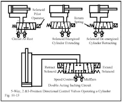
The 5-way valve in Figure 10-13 is found most often in pneumatic circuits. Although most hydraulic valve designs are 5-ported, the tank ports are connected internally by cored passages so only one external tank connection is needed. Air valves exhaust to atmosphere so having two exhaust ports is not a problem.
Notice the speed-control mufflers in these circuits. They reduce exhaust noise and act as meter-out flow controls. A 5-ported valve, especially if it’s spool type, can offer advantages when piping certain pneumatic circuits.
When this circuit is at rest, air pressure ported to the cylinder’s head end holds the cylinder in its retracted position. Meanwhile the cap end is exhausted to atmosphere. With the solenoid energized, cylinder-extending air is ported to the cylinder cap end while the head end exhausts. With the solenoid de-energized, the return spring shifts the valve back to normal and the cylinder retracts under power.
A 5-way spool-type valve also can be piped with dual inlets at different pressures -- to conserve energy, to smooth stroke times and speed, or to cause a cylinder to stroke at high speed. (See Chapter 13 on Flow Controls and Chapter 17 on Quick-Exhaust Valves for circuits to do these.)
At the bottom of Figure 10-13, the double-acting inching circuit uses a 3-position, 5-way valve with all ports blocked in center condition to cycle a cylinder. Within reasonable limits, the cylinder can be stopped and held for short periods. (See the note on 3-way valves from Figure 10-11 on the reasons for poor results in pneumatic inching circuits.)
Another center condition for a 5-way air valve is pressure blocked and cylinder ports open to atmosphere. This center condition can be used for mid-stroke stopping of a horizontally mounted cylinder.
Both 4- and 5-way valves can replace 2- and 3-way valves by plugging or not using certain ports to produce the desired function. This can save money in inventory and time when troubleshooting. Only one spare valve of a given size takes care of many problems on the floor.
Types of directional control valves
Directional control valve designs generally fall into three categories:
- sliding-plate valves
- poppet valves, and
- spool valves.
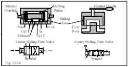
Sliding-plate valves use linear or rotary action to open and close ports to change flow paths. Figure 10-14 has a cutaway representation of each type. A linear sliding-plate valve usually is pilot- or solenoid pilot-operated to generate enough force to reliably move the lap-fitted linear sliding plate. As the hollow linear sliding plate passes over openings in the body, fluid is channeled to a working port or to exhaust through the hollowed out cavity or through the body. (Linear sliding-plate valves are used only in pneumatic circuits.)
Rotary sliding-plate valves are often manually operated. Some manufacturers offer a pneumatic or electrically powered rotary actuator for automatic operation as well. These valves are used in pneumatic and hydraulic circuits as control and/or isolation valves -- when high shifting speed is not needed. The seal between the rotary sliding-plate and the body can be lap-fitted or may have spring- and pressure-loaded seals to eliminate leakage.
