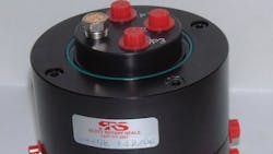
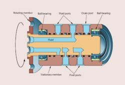
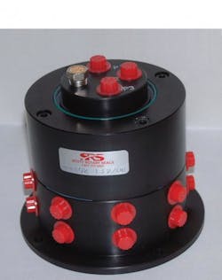
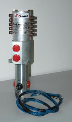
Rotating joints transmit fluid from multiple circuit lines through a single manifold that rotates continuously. Not surprisingly, then, they are often referred to as rotating manifolds. In general, fluid enters ports in the stationary half of the manifold and exits through ports on the other half, which rotates with the machine. A rotary seal between the two halves contains the pressurized fluid, yet allows relative rotation between the halves. Ball bearings at either end keep the two halves aligned under load and allow high-speed rotation.
The rotary seal is probably the most critical part of the device. This is because the seal between the rotating and stationary halves must be tight enough to prevent leakage of pressurized fluid, but loose enough to create as little torque drag as possible. Torque drag is a measure of the manifold’s resistance to rotation. These seals vary in complexity depending on the application. Rotating manifolds often use spring-loaded seals that apply seal force to prevent leakage when fluid pressure is low, while fluid pressure acts on the seal to prevent leakage under pressure. If the seal is not pressure balanced (fluid pressure acting on opposite sides of the seal), torque drag may increase with fluid pressure.
Configurations
As with any custom-engineered product, manufacturers can supply a rotating manifold to meet virtually any specification. However, standard options can be specified to provide near-custom design if four flow paths or fewer are required. Depending on their complexity and the standard product line of the manufacturer, rotating manifolds often are engineered items that must be special ordered, especially if more than four independent flow paths are required.
Standard configurations include straight-through and right angle — where outlet ports are perpendicular to inlet ports. A third configuration is offset, which is essentially a straight-through design with a 90° elbow integral to each end. Available space and fluid line routing generally determine which configuration should be used.
Keep in mind that axial length of a rotating manifold increases with the number of independent flow paths. In some applications, directional control valves can be mounted on the rotating end of the machine to allow routing only two common flow paths (pressure and return) through the rotating manifold. In this manner, all valves connect to the common flow paths through a conventional manifold or line fittings. Other considerations include through holes and integral valve.
A hole through the center of the rotating manifold can be specified as access for electrical lines, a shaft, or other machine elements that must be routed from the stationary member to the rotating one.
A specialty type of rotating manifold has built-in valves that allow or block fluid flow as the rotating member advances through a revolution. Internal passageways open and close as the manifold turns, allowing fluid to flow only when the rotating member is in certain positions — a setup that operates much like a mechanical cam. As with a cam, this arrangement is more difficult to reconfigure than using electrically actuated valves. However, it can be very practical for applications that have a repetitive, fixed operation — such as an indexing table.
Type of motion
Just as rotating manifolds should exhibit minimal friction to allow free rotation, hoses and piping should transmit as little external load to the manifold as possible unless it is designed with adequate bearings to support external loads. Otherwise, seals can wear prematurely and cause leakage. In extreme cases, the rotating joint itself may fracture.
Keep in mind that just the weight of components — hoses, tubing, and fittings — may be substantial enough to transmit an external load to the manifold. For example, the weight of a 10-ft section of spiral-wound hose may be overlooked, but can impose a substantial side load or bending moment on a manifold — especially when the hose is filled with hydraulic fluid.
Size and mounting
Obviously, the manifold must have ports of the correct size and geometry to accommodate hose and tubing assemblies mating to it. Ensure that enough clearance is provided between ports to allow threading and unthreading hose and tube fittings to the manifold. Also keep in mind the physical size of the rotating manifold. The more fluid lines routed through the manifold, the longer its axial length. The greater the flow through the manifold, the larger its required OD.
A means must exist to mount the swivel to the machine structure. Hose and tubing should also be connected to the structure close to the manifold to prevent misalignment and side loading that results from long runs of unsupported hose or tubing. Side loading can also be introduced by forcing misaligned rigid tubing into position for mounting. The assembly may fit together, but life and performance of the manifold suffer.
Selection considerations
When selecting rotating manifolds, not adhering to manufacturers’ specifications can result in leakage, premature failure, premature failure of hose, or all of these conditions. Exceeding manufacturers’ published pressure ratings can cause fluid leakage by pushing fluid past the manifold’s rotary seals. Excessive pressure can also increase friction, leading to premature wear and higher torque drag.
Also ensure that the rotating manifold is compatible with the application environment. The chemical composition and temperature of the fluid being used and the external environment are especially important when selecting the seal material. Whenever possible, mount the swivel joint where it will have minimal exposure to abrasive or corrosive particles.
About the Author

Leaders relevant to this article:


