This file type includes high resolution graphics and schematics when applicable.
Pressure sensors are the gateway between the physical world of pneuamtics and the electrical world of control systems. Designed to operate accurately and reliably in harsh environments for years, or even decades at a time, pressure sensors typically only garner attention when they fail, which is a rare occurrence. Smart designers know that paying close attention to these devices is necessary to ensure that the switch or transducer they choose delivers the optimal combination of performance, reliability, and solution cost for their particular application.
Even though only a handful of basic types of sensors exist, the selection process isn’t as easy as it might seem. Each type of pressure switch or transducer is available in a near-infinite combination of packages, ports, pressure ranges, electrical outputs, and connector styles, which can make selecting the best match for a particular job a challenging, time-consuming feat. The goal of this article is to familiarize you with pressure-sensor functionality and construction, and how that affects a particular pressure sensor’s suitability for a given application.
Pressure Sensors in Pneumatic Systems
Pressure-sensing devices play critical roles in pneumatic and hydraulic systems, whether helping to control a high-speed manufacturing system or monitoring various inlet and outlet pressures within an air compressor to determine performance and efficiency.
Industrial machines and manufacturing systems rely on pneumatic switches and transducers for information that enables them to move precisely and apply the required amount of force or torque.
Pressure-sensing devices can be categorized as either a switch or transducer. Pressure switches, relatively simple devices, indicate whether the pressure they’re sensing is above or below a predetermined threshold. Their output represents a change in the state of either an on-off switch or a two-state electrical signal.
A typical pressure switch consists of a contact driven by a diaphragm or piston, which is pushed in one direction by the fluid being sensed and a bias spring that pushes in the opposite direction. The switch’s contact changes state when the pressure on the switch’s inlet side rises above the pressure exerted by the bias spring on the other side. Conversely, the switch returns to its original state once the inlet pressure falls below a predetermined threshold. Due to a phenomenon known as hysteresis, that threshold may or may not be the same as its actuation level. In some cases, hysteresis can be used to one’s advantage when attempting to stabilize pneumatic systems.
Pressure transducers, on the other hand, are devices with continuously varying analog or digital output (voltage, current, resistance, I2C, etc.) that’s proportional to the pressure they see on their input. Several types of devices can translate a mechanical pressure into a detectable electrical signal, including piezorestistive transducers, whose versatility and cost makes them the most commonly used transducer.
Piezoresistive transducers operate on the principle that certain semiconductor materials, such as silicon, change resistance with stress or strain. These piezoresistive elements are implanted on a silicon chip attached to a mechanical sensing element (such as a diaphragm) or used as the sensing element. When a bridge circuit (e.g., wire filament strain-gage transducer) incorporates piezoresistive elements, it produces an analog voltage signal that’s proportional to the applied pressure.
Like most transducers, piezoresistive devices don’t react in a linear manner to pressure stimulus. They also exhibit a tendency to drift over time, or in response to environmental conditions. Traditionally, drift and nonlinearities were corrected by external means. Now, however, many modern transducers contain integrated electronics that linearize the sensing element’s raw output and convert it into one of several standard electrical voltage or current ranges. Many of these devices also provide some degree of stabilization against temperature and time-related drift.
A Switch or a Transducer?
Some applications, especially those involving detection of an upper or lower pressure threshold, make it tough to decide whether to use a pressure switch or a pressure transducer. This is most apparent in new products or radical updates of existing designs. It’s seemingly less of an issue for compressors, pneumatic control systems, and many other mature products and applications that already have well-defined requirements.
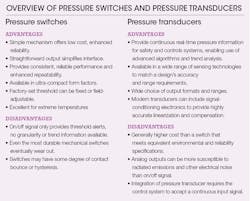
In fact, it’s probably useful to weigh your options for nearly every design project. Sometimes a new look at a mature design can yield fresh insights and unexpected improvements. The table summarizes general advantages and disadvantages of pressure switches and transducers.
Matching the Transducer to the Application
When your design does indeed require a pressure transducer, selecting the right device comes down to only buying the performance and capabilities you need, and avoid paying for those you don’t. In practice, that’s not always as simple as it sounds, but the following list of selection considerations should help ease the process. Once you’ve selected the criteria relevant to your application, determine the values that will meet your requirements.
Selection Considerations
• Pressure range: What are the anticipated maximum and minimum pressures for your application? Do you need to expand the range requirements above and below your formal requirements to cover unanticipated conditions? What are your units of measurement (psi, bar, mm Hg, etc.)?
• Accuracy and stability: How accurate does the pressure measurement need to be?
What is the tolerable maximum total error band (TEB) for the application? TEB is a comprehensive, clear, and meaningful way to express the transducer’s true accuracy over a compensated temperature range with respect to a variety of different potential error sources. Honeywell’s PX2 series, for example, offers TEB of ±2% across a temp range of –40 to 125°C (–40 to 257°F).
• Signal conditioning: Should the transducer output its readings as a voltage, current, or resistance?
What output range do you need from the transducer, and in what type of units?
• Electrical and EMI protection: What is maximum level of electromagnetic interference (EMI) you’ll need your application to operate reliably in? What are the highest levels of EMI and extraneous voltage your application’s transducers must be able to survive without damage? For example, Honeywell’s PX2 series provides protection up to 100 V/m (ISO 11452-2 certification available).
• Environmental conditions: What’s the required operating temperature range?
What are the maximum tolerable levels of shock and vibration? Many Honeywell pressure transducers are rated for 100G (per MIL-STD-202F, Method 213B, Cond. F, and a vibration rating of 20 G sweep, 10 Hz to 2000 Hz). What ingress protection must a transducer meet to work in application conditions?
• Media compatibility: What’s the temperature range of the media being measured? Does it have corrosive properties?
• Packaging and mounting options: The environmental, media compatibility, and mechanical issues you’ve already considered will provide lots of guidance on the packaging requirements for a stand-alone transducer. But for some applications, it may be worthwhile to consider a board-mounted transducer that’s co-located with the application’s other electronics. Board-mounted pressure transducers can provide space-saving solutions with specialized port options, giving the transducer access to the gas or fluid being monitored while it resides within the electronics module’s relatively benign environment.
• Mechanical and electrical interfaces: Does the application have any specific mounting holes, brackets, or other hard points the transducer needs to attach to? If so, what holes, flanges, or other features does the transducer housing need to have to mount where it’s needed? What are the types of pressure input fittings and electrical connectors that are required for the transducer?
• Additional considerations: Will the operating environment pose any additional challenges (vibration, rapid temperature cycling, corrosive vapors etc.)? What type of pressure will be monitored—gauge, absolute, differential, or sealed? Does the application pose any size or cost constraints?
This file type includes high resolution graphics and schematics when applicable.
Conclusions
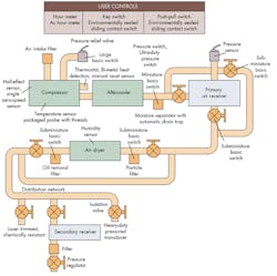
With this basic understanding for selecting the right pressure sensor to meet design objectives, it’s time to apply this knowledge. These principles can be applied to a more complex real-world application, say, a whole-plant air compressor used in manufacturing for operating presses, pick-and-place and other production machines, and air tools used in assembly operations. Proper placement of switches and transducers can provide a link between the plant’s pneumatic and electronic control systems. This tie-in makes it possible to monitor production; conduct statistical process control; aid troubleshooting by identifying operating parameters that fall out of tolerance; and even conduct proactive maintenance by examining changes and trends in pressure that signal necessary actions to be taken before there’s an occurrence of failure.
To do this, you must have a clear understanding of your application’s job, how it does that job, and its targeted environments. Once that’s done, following the questions and suggestions offered in this article will help narrow your search to the handful of choices that offer the best mix of performance, reliability, and total cost of ownership.
Ketan Mehta is Senior Product Marketing Manager at Honeywell’s Sensing & Control Group, Minneapolis.
About the Author

Leaders relevant to this article:


