∆P gauge quickly spots leakage
Fluid power assemblies must be tested for leakage. The three traditional, low-tech approaches for doing so are:
- Filling the assembly with compressed air, then slopping soapy water on it to see if bubbles reveal leaks.
- Immersing the whole assembly in a water bath, then pressurizing it with air — again, watching for bubbles.
- Pressurizing the sealed assembly and watching a gauge for pressure decay.
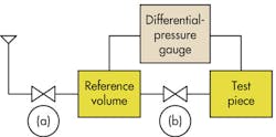
At best, these methods are cumbersome and time-consuming. At worst, they add drying and corrosion problems. All interrupt production flow. A simple, high-speed leakage test, suitable for production work, can be assembled from a differential-pressure gauge, a pair of two-way valves, and a vessel that is known to be leak-free. The circuit is shown in the accompanying illustration.
The leakage rate can be calculated from the formula:
L = (∆P × VS)/(PA × t),
where L = flow, in scfm; ∆P = differential pressure, in psi; VS= assembly volume, in ft3; PA = atmospheric pressure, in psi; and t = time, in minutes.
Joe Gordon, chief engineer, Differential Pressure Plus Inc., Branford, Conn., suggested this test configuration. Call him at (203) 481-2545 for more information, or visit www.differentialpressure.com.


