Closed-loop electrohydraulics upgrades bearing tester
Napoleon Engineering Services specializes in bearing inspection, testing, and custom bearing manufacturing. Headquartered in Olean, N.Y., officials at NES were looking for a way to improve operation and performance of a bearing test machine, so they sought design assistance from Callahan Motion Control, Darien Center, N. Y. Together with Callahan, Napoleon developed a new bearing test rig with greater productivity and better quality control by incorporating electrohydraulic proportional control using higher-response pressure- and flow-control valves and a four-axis motion controller.
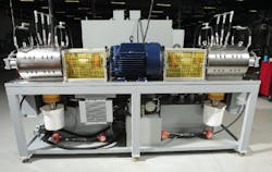
Callahan’s Gary Cotton explained, “This particular test rig has a double-shaft electric motor that provides enough power to test up to eight bearings at a time. Aside from the electric motor, which provides rotational power for testing, the rest of the test system relies on hydraulics. The bearing test rig consists of 10 proportional valves to control hydraulic fluid to two axial loading cylinders, two radial loading cylinders, and lubricant flow to the bearings undergoing load tests.”
Closed-loop force control
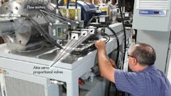
Cotton continued, “The machine’s main force control system consists of a variable-displacement, axial-piston pump with pressure compensation feeding four Atos DLHZO-TE-040-V11 servoproportional valves for controlling the cylinders that apply loads to the bearings undergoing testing. These valves have LVDT spool position feedback and on-board electronics. The valves can flow up to 1.3 gpm each at a 435 psi ∆P and are extremely quick, with response of less than 10 msec. The PLC and load cells originally used were much slower, thus creating an unacceptable overshoot when applying loads.”
To overcome these problems, an RMC 150E H2-DI/0 four-axis motion controller, from Delta Computer Systems, Battle ground, Wash., was specified to close the control loop on all force control axes. Cotton offered, “The motion controller has a pressure (force) control feature to process the feedback signals from load cells on the cylinders. The forces applied to the bearings are now typically held to less than 0.5%. One individual test was set at 33,000 lb of radial load and stayed within a ±45 lb range throughout the test cycle.
“An unforeseen snag in the retrofit was that even with a pressure compensated pump, the force control system began overheating when operated at pressures greater than 2500 psi. A kidney loop (offline cooling and filtration circuit) was subsequently added to fix this problem.”
Cotton added, “The test stand has two additional power units run by low-pressure gear pumps. These circuits feed six Atos QVHZO-AE-06/12/PE pressure-compensated proportional flow control valves with controlled-temperature lubricant to the bearing specimens. These valves can be set individually to supply from 1.5 in.3/min to 3 gpm to the various bearing lube ports.” Flow meters in these lines generate feedback signals to the controller for continuous monitoring.
A touch-screen display on the control panel allows the operator to individually monitor, set, and adjust the bearings’ rotational speed, all four force settings, and all six lubricant flow rates. The operator can also monitor other functions, such as fluid temperature, vibration, bearing torque, power consumption, etc. The system is able to download performance data to a PC for system analysis.
Upgrades make a difference
“Overall, this system makes it much quicker and easier for initial parameter setup on the touch screen display and allows the operator to continuously monitor all critical functions in real time,” explained Cotton. “Previous designs required manual adjustment of all flow- and pressure-control valves. Prior to the new closed-loop system, values changed from day to day and even during the course of the day from viscosity changes of the fluid. Because of the rapid response and extremely fast characteristics of the chosen valves and axis controller, this new system has much higher repeatability and stability than previous test rigs.”


