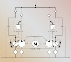
Pumps on stretching machine blowing up
Officials at a stainless steel rolling mill purchased an old but well-built plate stretching machine. They had us strip the machine of all the hydraulic and electrical controls because they wanted us to design and install new hydraulics and a PLC to control the stretcher. This machine would clamp both ends of a 12 × 20 ft stainless plate they had heated and rolled to a thickness that could be up to 1½ in. thick. The process of heating and rolling to size caused the plate to warp, making it look like the waves of an ocean.
The circuit shown is for the hydraulic pump-motor system mounted on top of a 500-gal tank. It consisted of a 300-hp electric motor and a large vane pump with a pressure compensated piston pump piggybacked to it on both ends of the motor. This power unit’s single pressure outlet was plumbed to a cartridge valve manifold. The manifold valves would clamp theIn the neutral position, the main pressure line was blocked, causing the vane pumps to unload and the pressure compensated pumps to compensate. The hydraulic system also had a separate filter-cooling loop, not shown in the drawing.
When our technicians started the system up to bleed air and set the pressure, one of the large vane pump’s housing blew apart! Fortunately, no one was hurt. They double-checked the plumbing and confirmed everything was installed correctly. The damaged pump coupling was disconnected and they re-started it again with the same results—the other large pump was in pieces.
Any idea what caused the problem?
Robert J. Sheaf, Jr. is the founder of Certified Fluid Consultants (CFC) and President of CFC-Solar Inc. CFC-Solar provides technical training, consulting, and field services to any industry using fluid power technology. Visit www.cfc-solar.com for more information.
|
Find the solution Think you know the answer? Submit solutions to [email protected]. The correct answer will also be published in the next edition of “Troubleshooting Challenge.” All correct solutions will be entered for a chance at a $50 gift card — we will randomly select a winner from all correct answers. The winner’s name will be printed in the next edition of “Troubleshooting Challenge.” |
|
Solution to March's rebuilt HST problem The potash mine conveyer lift problem on the original hydraulic pump suffered severe cavitation or aeration damage. This problem should not occur if the intake of the pump is maintained at approximately 250 psi or higher. The passages in the pump are designed for the maximum pump flow with minimum pressure drop, thereby keeping any implosion damage from cavitation or aeration to a minimum. If the shuttle relief is located 600 ft below the pump, the weight of the column of oil being pushed up to the pump causes about 240 psi. Add this to the 250 psi pressure needed at the pump inlet, thus requiring the shuttle relief to be set at about 490 psi. Unfortunately, the 490-psi backpressure at the motor would reduce the torque output of the motor. When the calculations were made, the torque output of the motor was based on the maximum pump pressure setting with a 200-hp diesel engine. The charge pump backpressure needed to be considered when making this calculation. We found that if the shuttle relief was lowered to 250 psi, reading it at the motor, the system would lift the normal potash load. However, the inlet gauge at the pump only showed about 50 psi. This pressure was not enough to minimize the cavitation damage experience by the original pump. We also wondered why the low charge pump pressure did not cause stroking and response problems. On further examination, we found a 125-psi check valve was installed just before the charge pump pressure filter, providing about 175 pi for control pressure. The mine manager had another diesel engine rated at 245 hp. With the larger engine, we were able to increase the main pressure and have the pump inlet pressure at 250 psi. Not only did this solve the problem, they were able to lift more tonnage each shift. |
About the Author

Leaders relevant to this article:

