Situated on the border of Georgia and Florida is the Jim Woodruff Lock and Dam. The dam impounds Lake Seminole, producing hydroelectric power, and its single lock provides navigable access to the Chattahoochee River.
Hydradyne LLC, Tampa, Fla., recently completed the design, fabrication, and installation of the new hydraulic systems at the dam. Construction of the lock and dam began in 1947 and was completed in 1957 by the U. S. Army Corps of Engineers. The dam feeds a hydroelectric power plant containing three turbines with a combined rated output of 36,000 kW.
The dam’s original hydraulic system consisted of one central power unit located on the second floor of the northeast tower and two hydraulic operator stations on the east wall. The original hydraulic power unit served eight cylinders; each of four operates a miter gate, and the other four operate two upstream and two downstream water valves, which fill and drain the lock. Considering the fact that the lock chamber is 82-ft wide by 450-ft long with a maximum lift of 33 ft, a tremendous amount of welded pipe was installed to interconnect all system assemblies. Tunnels were constructed under both ends of the lock in order to run the hydraulic lines to the west-wall machinery.
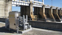
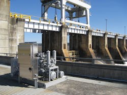
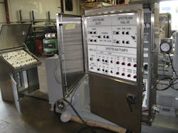
The new system design consists of four identical hydraulic power units placed at each corner of the lock and two stainless-steel electric operator consoles positioned on the east wall of the lock facing the water. Each power unit operates one 12-in. bore miter gate cylinder and one 11-in. bore water valve cylinder. Because the water valves were designed to allow a water rise rate of 10.25 fpm, continuous visual contact with boaters in the lock was mandatory. Another desired feature was to include redundant controls mounted on the front face of each power unit enclosure with a hinged, lockable stainless-steel cover. The cover protects the controls from the environment and can also prevent someone from operating more than one control station at the same time.
The power units were designed for outdoor service in all weather extremes. The top surface of the 250-gallon reservoir has a 5° slope to prevent water ponding. An immersion heater in the reservoir was sized to maintain oil temperature at 70°F during the winter months. The reservoir also contains magnetic separators, a level and temperature gauge, low oil-level switches, a dual-setpoint temperature switch, pump-suction shutoff valves, suction strainers, and desiccant breathers. Two Parker axial-piston pumps, a duplex high-pressure filter, and an in-tank return filter provide system redundancy. A drip pan with drain valve was also included.
Control Center
Each of the six operator control panels also contains a keyed switch that allows the operator to select “off,” “remote,” or “local” mode providing an additional safety lockout feature. The operator would start one of the redundant west-wall and east-wall pumps and then operate the gate or water-valve cylinders in manual or automatic mode. In manual mode, the operator manually selects fast or slow speed at any time during the sequence and holds down the appropriate pushbutton. In automatic mode, the operator would momentarily depress the gate or valve open or close pushbuttons to initiate a programmed sequence. Four magnetic proximity switches were mounted along each cylinder mechanism to provide position feedback. In automatic mode, the gate or valve cylinder starts at slow speed, accelerates to high speed, slows down, and then stops at the full open or closed position.
The control panels also monitor high oil temperature, low oil level (warning and shutdown), and status of the high-pressure and return-line filters. Since differential pressure switches on filters operate only while fluid is flowing, the PLC was programmed to lock in the filter indication lights until the operator installed a new filter element and depressed a reset button. An emergency stop palmbutton was also included on each operator panel.
A new motor-control center was installed to provide power distribution to the hydraulic units. Each power-unit enclosure contained pump-motor starters, an immersion heater contactor, a 60-A transformer for external lighting, a 30-A welding receptacle, a control-voltage transformer, and a PLC. Each electric motor was provided with encapsulated windings and winding heaters. System communication was accomplished using an Ethernet/IP fiber-optic ring network. It was imperative that logic be transferred between the power-unit PLCs for control and safety interlocks. Allen-Bradley produced the tag protocol that was utilized for the logic transfer.
A custom manifold contained all valving required to operate the miter gate and water valve cylinders and included: flowmeters, directional-control valves, counterbalance valves, cylinder-port relief valves, pilot-operated check valves and a high-speed/low-speed circuit. The high-speed/low-speed circuit consisted of a low-flow, pressure-compensated flow-control valve and a full-flow normally-closed DIN-style solenoid valve. When the high-speed valve is energized, full pump flow bypasses the flow control allowing full cylinder speed. Orifices in the DIN valve allowed smooth transition from full speed to low speed. Synchronizing two opposing gates during high speed was accomplished by visually adjusting the pump maximum volume stops.
The rear face of the manifold contained four-bolt flange ports for the cylinder connections. New stainless-steel welded pipe was installed between each manifold and the cylinders in the existing concrete trenches. Two stainless-steel ball valves at each cylinder location were provided to isolate the cylinder and a third bypass ball valve allowed the new pipe to be flushed prior to commissioning of the system. The manifold also contained several pressure test ports for system monitoring and evaluation.
Finishing Up
The miter gate cylinders and water valve cylinders were the only components used from the original system. During installation of the new hydraulic system, the cylinders were removed from the lock and sent to Hydradyne’s facility for teardown and inspection. Cylinder barrels had scoring and rust, the chrome rods were pitted, and several cylinders contained 50 years’ worth of contamination. The cylinder barrels were honed, the rods were rechromed or replaced, new cast-iron piston rings were installed, and all of the seals were replaced.
Prior to shipment to the job site, all four systems were hydraulically and electrically interconnected at Hydradyne’s facility to conduct a complete functional shop test. Onsite system commissioning included pipe flushing, hydrostatic testing, oil particle and water-content analysis, as well as complete functional system testing.
BOB NASCA is National Systems Engineer for Hydradyne LLC, Tampa, Fla., (www.hydradynellc.com). Nasca is the author of the book, Testing Fluid Power Components. It is available on Amazon.com by clicking here.
About the Author

Leaders relevant to this article:


