Software Helps Develop Subsea Systems
This file type includes high resolution graphics and schematics when applicable.
Deep-sea drilling operations often require hydraulic power at the seabed to actuate emergency blowout prevention (BOP) valves or other flow controls. Sometimes, large pre-charged accumulator arrays can be installed close to valves to provide a quick source of hydraulic power. However, in one recent study of an application, a downhole valve was located 2,000 ft. below its hydraulic power source. Some of the questions for the system designer that arose were:
- How long will it take to charge the accumulators?
- What will be the charging equipment requirements?
- How does hose compliance affect the response time and fluid volume required?
- Will there be any issues with water hammer transients?
- How do temperature changes affect the response at operating depths?
Hydraulic systems are often highly non-linear in nature; consequently, the relationships between pressure, temperature, flow, and motion are complex. For critical systems such as BOP valves, careful design mandates the use of software simulation to accurately predict the system performance and explore how the designs respond to different scenarios. For this project, Easy5 software was chosen as the modeling tool.
Summary of the Software
Easy5 engineering software is used to simulate dynamic systems characterized by differential, difference, differential algebraic, and algebraic equations. This spans a broad range of applications, such as mechanical, electrical, hydraulic, pneumatic, thermal, gas dynamics, powertrain, vehicle dynamics, digital/analog control systems, and more. Models in Easy5 are assembled on-screen from application-specific libraries of components (such as pipes, valves, actuators, fuel cells, and gears) and from general-purpose modeling blocks (e.g., summers, dividers, lead-lag filters, and integrators). The advanced application libraries available from MSC include:
Thermal hydraulic—Pipes, orifices, hydraulic valves, pumps, actuators, heat exchangers, and reservoirs are provided for modeling a wide range of hydraulic components. This library has been widely applied in the aerospace, off-road vehicle, and heavy machinery industries, as well as in oil and gas exploration. A compressible fluid formulation is used throughout the library, enabling accurate prediction of transient performance.
Gas Dynamics (including pneumatics)—Pipes, orifices, pneumatic valves, compressors, and heat exchangers are included. Gases may be treated as ideal if appropriate, or a range of non-ideal gas models is available.
Electric systems—Contains AC and DC machines, power components, and basic circuit elements for analysis of electrical actuation, power electronics, and power transmission.
Other application libraries are also available for modeling aerospace guidance systems, vehicle powertrains, internal combustion engines, and fuel cells. Interdisciplinary systems can readily be simulated. For example, Easy5’s Thermal Hydraulics and Electric Systems libraries can be used together to analyze an electrically-actuated hydraulic system.
Modeling and Analyzing the System
A charging module consisting of a high-pressure, 10-gpm pump, reservoir, and associated valves and controls was located on a drilling platform in the North Sea. Standard 10,000 psi, 1-in. hoses connected the charge module to a BOP power pod located 2 miles away and 7,000 ft. below sea level. The completed borehole, located near the BOP pod, had a gate control valve placed 2,000 ft. deeper, to a depth of 9,000 ft.
Many elements of a standard ISO engineering hydraulic schematic correspond to components available in the Easy5 libraries. Icons representing the components are dragged-and-dropped onto the computer display and placed similarly to those in a schematic drawing.
Data connections, often representing instantaneous values of flow, pressure, signal level, and fluid properties, are established by clicking first on the upstream and then the downstream component. The designer generally is not concerned with what quantities need to be communicated because Easy5 automatically makes the correct data connections.
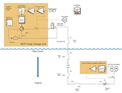
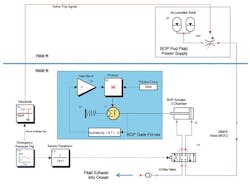
The software model was divided into two segments: the charging portion and the valve actuation system, depicted in Figs. 1 and 2, respectively. Both schematics include software components from the Easy5 Thermal/Hydraulics Library that model the physics of the reservoirs, hoses, pipes, pumps, valves, orifices, actuators, and other components found in hydraulic systems. The data connections are represented on the drawings by lines; actual fluid conduits, such as pipes, have their own icons.
The bulk modulus of the fluid (ethylene glycol/water/miscible oil) was also taken into consideration. Depth effects and instantaneous pressure, temperature, and heat transfer changes all contributed to the simulated response. The accumulators are represented by components from the Easy5 Pneumatics Library, which use real-gas equations of state. Both model segments assumed that hoses and other components were initially filled with fluid at the ambient pressure and temperature.
This file type includes high resolution graphics and schematics when applicable.
Operation Sequences
This file type includes high resolution graphics and schematics when applicable.
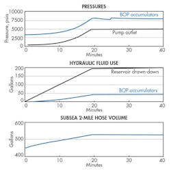
In the charging sequence, fluid at 55° F is pumped into the system until the pressure in the accumulators reaches 8,000 psia. At that point, the supply valve isolates the accumulators, the surface pump shuts down. The simulation results, shown in Fig. 3, point out that it requires more than 200 gal of fluid at atmospheric pressure and temperature to pressurize the accumulators (pre-charged with nitrogen to 3,000 psia) with 40 gal of fluid at 8,000 psia.
Some of this extra fluid is consumed in the expansion of the hoses as they pressurize, and some is due to the increasing density with pressure and the decreasing temperature with depth, as the seabed ambient temperature is not much above freezing. As the fluid reaches design pressure at the accumulators in about 20 min, the controls shut the supply valve; the pressure then drops as the fluid cools. This action restarts the filling cycle until the pressure finally stabilizes in 30 min.
To achieve the required pressure, the threshold on the supply valve must be set somewhat higher than the required pressure and the gain adjusted to avoid repeated cycling of the pump. This is accomplished by running the simulation and changing the parameters until requirements are met. Data from the simulation showed that the pump required up to 43 hp during the charge cycle.
Investigating the gate valve closure in the borehole required a second model, depicted in Fig. 2. A sensor near the valve location determines when the valve should close. An affirmative signal opens the BOP pod main valve at the accumulators and sends high-pressure fluid through a 2,000-ft, 1 in. hose and down 9,000-ft. to the valve. An actuator then closes the gate valve to seal the borehole. The forces that must be overcome to close the gate are variable. In this model, the roughly 2,000-lb. force was represented with both coulomb friction (opposing the motion) and a spring. The small amount of fluid used to operate the valve is exhausted to ambient through a check valve.
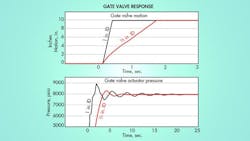
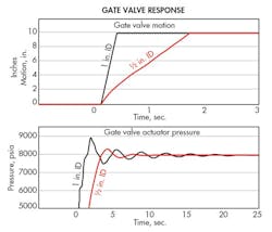
Simulations of the closing sequence, with results shown in Fig. 4, reveal that it only takes about ½ sec for the valve to close the 10-in. borehole. However, a significant pressure overshoot (circled in the figure) of 1,000 psi occurs from a water-hammer transient between the fluid supply and the control valve. Reducing the supply valve opening diameter did not significantly impact the overshoot. Placing an accumulator near the control valve would reduce the effect, but space considerations eliminated this option. Fortunately, parametric studies with the model showed that reducing the ID of the hose from 1 in. to ½ in. significantly mitigates the transient maximum pressure (the red curve in Fig. 4). It takes longer to close the gate valve with the reduced flow rate, but this was tolerable. As a side benefit, the smaller diameter hose was a significant cost saving. The simulation time on a standard laptop required only a few minutes for each case, so several design experiments could be run economically.
Reviewing Benefits
A simulation tool such as Easy5 gives designers a significant edge when faced with challenging fluid power control issues. The ability to rapidly prototype a system and run parametric studies is only one aspect. Customized, reusable software libraries can be built to capture the proprietary knowledge of experienced engineers and make it available to other designers. Existing systems can be modeled—and problems isolated and identified—without resorting to physical testing.
Claude Ginsburg and Daniel Thomas are senior development engineers at MSC Software Corp., Newport Beach, Calif. For more information, call (714) 540-8900.
This file type includes high resolution graphics and schematics when applicable.
About the Author

Leaders relevant to this article:
