Myth #5: Higher pressure reduces component sizes
It is generally accepted that as system operating pressure increases, component size diminishes because power can be transmitted more from pressure than from flow. That is, power is the product of pressure times flow Therefore, as pressure rises, flow can decrease for the same amount of power. And component volume (size) can commensurately be decreased for the same amount of power.
Several years ago, the Milwaukee School of Engineering’s Fluid Power Institute conducted a survey regarding the expected trends and forecasts, expected in hydraulic system design technology. Questionnaires were distributed to several design engineering departments of mobile equipment manufacturers. Although the surveyors made no claim as to the scientific veracity of the survey or results, the responses, nonetheless, were interesting. If the trends and forecasts at the time of that survey had been accurate, we would now see systems routinely operating at 10,000 to 15,000 psi. That has not happened.
Feeling the pressure
Perhaps a new survey is required to scientifically determine the reasons why pressures have not migrated to such stratospheric levels. In the meantime, I offer my personal opinions. There is likely a reluctance to manufacture systems that operate at very high pressures because of an unwanted exposure to product liability. Another reason is that all components within the system must be capable of reliable operation at high pressure: cylinders, pumps, filters, plumbing, seals, fittings, manifolds, etc. The system pressure is limited by the most vulnerable component.
Additionally, as pressures increase, component wall thicknesses must also increase. There comes a pressure level where any further increases in wall thickness will result in component weight and size increases, even though the hydraulic volume may be diminishing. These several factors have worked to place a ceiling on the maximum working pressures in otherwise high pressure systems.
Now, all that background having been said, designers still have a broad range of pressures to use for system designs, in both industrial and mobile equipment. Maximum practical pressures are now as high as 7000 psi. It begs the question, “How high should system design pressure be when the value is completely arbitrary?” And the correct answer to the question: “It depends.”
A limiting factor
The arguments for minimizing size have been stated above, but a more subtle factor all too often is ignored when designing systems: hydromechanical resonant frequency. As design pressure goes up, component size generally goes down. However, the resonant frequency goes down as well.
It has been argued many times in previous editions of “Motion Control” that low resonant frequency results in systems that are springy and bouncy, and that can be difficult to control. This is particularly problematic when using closed-loop control, which is finding increasing use in all manner of systems. But this can be bothersome even in manually controlled mobile equipment.
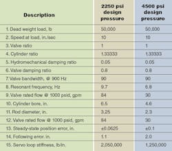
An example problem will help point out the differences: Assume you must move a 50,000-lb dead weight load vertically at 10 in./sec with a cylinder that has low-friction seals and very little other friction loading. The example is set up to compare the results when the power unit supplies a constant 2250 psig to those when the power unit supplies a constant 4500 psig. Optimal sizing technology has been applied to obtain the solution. The table shows the results of the two designs.
System comparison
The values in red are the design objectives, and the values in blue are the calculated results. This display ploy has been used to emphasize that in both cases — 2250 psi vs. 4500 — the force-velocity goals as well as other parameters are identical. In this way, we can easily see the effect only of changing the system design pressure.
Item 8 in the table is the key calculated parameter. With the lower pressure, the frequency is 9.7 Hz, but it drops to 6.8 Hz when the design pressure is raised to 4500 psi. There is about a 42% increase in the resonant frequency for having lowered the pressure. Many times this will mean the difference between a successful and a failed application.
Another important parameter is Item 15, the servoloop stiffness. Because it uses a position transducer and feedback control, it is generally believed that a servoloop is infinitely stiff. That is another misconception to be covered in a future issue. The proportionally controlled positional servoloop behaves like a spring. When the pressure is 2250 psi, the stiffness is 2 million lb/in. However, with the higher pressure, stiffness drops to about 60% of that value. The stiffness is a measure of the servoloop’s ability to hold its position against a varying load. The higher, the better.
Note also the positioning errors in Items 13 an 14. Item 13 is a measure of the servoloop’s ability to achieve a commanded position in steady state. With the lower pressure, it will find commanded position within 0.0625 in., whereas it can only find it within 0.1 in. with the higher pressure.
However, the added performance does not come for free. There is a price to pay that cannot be ignored. The price is in the valve size and the cylinder size. The cylinder bore is about 41% greater with the lower pressure. And because the goal with both pressures is to get 10 in./sec of speed, the valve flow rating goes from 30 to 84 gpm! This is not at all unexpected. After all, the purpose of using higher pressure is to make component sizes smaller.
In summary, the system designer must juggle some competing results. There has to be compromise between resonant frequency, component size, and cost. All too often, the higher pressure results in lower cost and — more often than not — lower weight components, and that is the final choice. However, if stiffness and resonance are limiting final performance, it may be necessary to downsize the pressure and upsize the cylinder and valve. It all depends on whether dynamic performance is more important than initial cost.
How to deal with hydromechanical resonant frequency
Ever wonder how hydromechanical resonant frequency crops up as a problem in hydraulic systems? If so, you’ll probably want gain an understanding of the challenges and causes of hydromechanical resonant frequency. Two resources dramatically illustrate how low resonant frequency and low damping can produce totally unacceptable machine behavior and what to do about it. These videos should be useful to anyone required to make hydraulic and electrohydraulic machines operate smoother, faster, quieter, and more reliably while getting the shocks and vibrations out of the system.
Effects of Inertia on the Hydraulic Servo Mechanism shows a cyclic machine, typical of many industrial and mobile applications, that is subjected to an ever-increasing inertial load. Machine operation is monitored by position and pressure transducers with outputs displayed on an oscilloscope. Merely by looking at the behavior of the machine, it is obvious that high inertia and low damping have a devastating effect on system performance. The video consists of 24 minutes of lab footage showing the effects in real time. It also contains a one-hour lecture explaining what is happening in the video. The aim was to be instructional, and it successfully achieves that goal. A workbook accompanies the video.
Four Methods for Controlling the Difficult Machine takes on the challenge of designing around a system plagued by high inertia and low damping. Such machines are referred to in the video as “difficult machines,” for reasons that are obvious in viewing their operation. This video tackles the difficult machine head-on and shows four different methods available to the systems design engineer when high inertia and low damping must be accepted. The methods are both hydraulic and electronic and include controller software possibilities. Again, the video contains actual lab footage of the machine in operation, including footage showing the effectiveness of the four different corrective methods. A one-hour lecture gives a detailed explanation of the concepts behind each of the four methods, and a workbook accompanies the video.
For more information or to order, visit the H&P Bookstore by clicking here.


