The Basics of Small-Bore Fittings
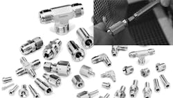
Small-bore tube fittings represent one of the most important components for fluid-handling systems. They are installed at critical connection points where they must deliver leak-tight performance to contribute to operational safety and efficiency. They are used to connect a wide range of fluid system components, including tubing, hoses, valves, regulators, filters, and sample cylinders, as well as various measurement devices such as flow sensors, pressure gauges, pressure transducers, and thermometers.
Small-bore systems can carry chemicals and hydrocarbons in refinery applications, active ingredients for pharmaceutical manufacturing, exotic gases for semiconductor wafer fabrication, steam for process heating, and industrial air for manufacturing operations. Such systems may move air, various gases, or any of a wide range of fluids.
There are many different fitting options to choose from, with each type suited for different needs. So, how do design teams determine the right choice for their applications? Here’s a look at the options available and where each design can be advantageous.
Threaded Fittings
Threaded fittings are one of the most common options for securing connections with two threaded pieces. The first is male with threads on the outside of the fitting; the second is female with threads on the fitting’s interior. The connection is formed when the male threads are twisted into the female threads and secured by tightening the connection.
Many available threaded fittings adhere to either the British Standard Pipe (BSP) or the National Pipe Thread (NPT) design standard. (Per specifications, small-bore tubing and fitting applications range in size up to 2 in. (50 mm) for the tubing outer diameter).
There are two types of threaded fittings:
Tapered threads seal as the male and female threads are drawn together. These fittings are built at an angle in relation to the centerline (straight threads, by comparison, are parallel to the centerline). A thread sealant or thread tape fills in gaps between the crests (peaks) and the roots (valleys) of the threads to prevent leaks. Tapered threads are typically effective for system pressures up to 15,000 psi.
Parallel threads, also known as straight threads, seal as the flanks of the threads are drawn together; there is no interference between the flanks, crests, and roots of parallel threads. Installing them calls for supplemental items, including gaskets, O-rings, or metal-to-metal contact to create leak-tight seals. Parallel threads are typically used in applications with system pressures of 5,000 psi or less.
When not dictated by pressure requirements, the choice between parallel and tapered threaded connections typically comes down to simple user preference. When considering which to choose, it can help to standardize the use of one type versus the other throughout a facility to reduce the potential for confusion or misapplication.
Compression Tube Fittings
Compression tube fittings are another common option. They use ferrules to create leak-tight seals, not threads. Compression fittings are also simple to assemble and disassemble.
There are two primary types of compression fittings: single ferrule and double ferrule.
- Single-ferrule compression fittings incorporate one ferrule to create a seal. The ferrule gets compressed between the nut and receiving fitting when the nut is tightened. The ferrule then bites into the tube, creating tube grip and body sealing action.
- Double-ferrule compression fittings include a front ferrule and back ferrule. Each has its own function but works together with the other. The front ferrule creates a seal between the body and tube, while the back ferrule grips the tube.
It is important to understand how the back ferrule bites into the tube, as not all tube fitting designs are alike. The reliability of a compression fitting’s tube grip is related to how well the back ferrule bites into the tube.
There are a few design differences between compression tube fittings, and those differences may affect performance. For example, a bite-type ferrule, whether it is a single or double ferrule design, bows during assembly. Bowing drives the leading edge of the ferrule into the tube to indent the tube surface, creating its grip.
However, any vibration, pulsation, thermal shock, or side load on the fitting may compromise the minimal contact of the single gripping ferrule. In a dynamic fluid system, the potential for either damage to the tube or pullout may exist. (Pullout refers to the tubing pulling out of the fitting connection due to other forces, such as vibration, causing the tubing to back out.)
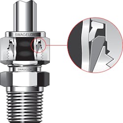
An even stronger grip and seal are created by fittings featuring a two-ferrule, mechanical grip design that delivers hinging-colleting action. This radial hinging-colleting action of the back ferrule grips the tube next to and outboard from the swaging point to improve vibration endurance. The hinging colleting action forces the mid-portion of the back ferrule to press onto the tube while keeping the back end of the back ferrule away from the tube surface. This creates direct and axial support to the tube-gripping function. This design also reduces the likelihood of fittings backing off in dynamic applications.
By creating long lines of sealing contact between the ferrules and tube, mechanical grip designs result in reliable gas seals. They are a good choice for applications where leaks cannot be tolerated.

Finally, medium-pressure mechanical grip fittings are an evolution of two-ferrule compression fittings. They consist of a female fitting body, a male nut, and pre-oriented ferrules. These fittings deliver outstanding performance and enhanced installation efficiency. They use a hinging-colleting action similar to two-ferrule tube fittings. This design creates a unique dynamic wedge for a stronger bite into the tubing. The design also lets fitting connections be disconnected for maintenance and then reconnected rather than replaced.
When remaking such connections for medium-and high-pressure applications, operators may tighten them by a standard wrench or a torque wrench to recreate the original leak-tight gas seal. (Medium-pressure applications range from 6,000 to 20,000 psig. High-pressure applications go up to 60,000 psig.)

Medium-pressure mechanical grip fittings also have a preassembled cartridge that holds the two ferrules and nut, helping ensure proper ferrule orientation during installation. These fittings can reduce installation time and lower assembly and maintenance costs while providing more reliable connections.
Cone and Thread Fittings
Cone and thread fittings are another widely used type of fitting. They are available in a variety of alloys and have several design features that suit medium- and high-pressure applications. Cone and thread fittings have been a standard choice for demanding, high-pressure applications for many years.
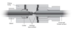
A cone and thread fitting will feature a gland, a collar, a female port, and a weep hole that lets technicians detect leaks and verify proper installation. In high-pressure applications, thicker-walled tubing is typically required.
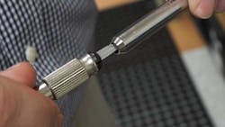
Installing cone and thread fittings is complicated and requires coning and threading tools, along with cutting lubricants, but can result in long-term reliability when performed correctly. Installers must properly cone and thread the tube before joining it with the fitting. Here, it is critical to remove any burrs, gouges, or scratches in the tubing.
After preparing the tubing, a collar is threaded onto the tubing and a gland nut is inserted into the fitting body for final tightening. To extend the life of tubing connections in systems that experience regular shock or vibration, it is recommended to use antivibration components.
Small-bore fittings may be made in a range of materials, including stainless steels such as 316 SS, 6-Moly alloys, and 2507 Super Duplex, as well as other alloys, with 316 SS being the most common choice. When specifying 316 SS, design teams should consider using metals with higher concentrations of chromium and nickel than the minimum American Society for Testing and Materials (ASTM) guidelines. ASTM calls for a minimum of 10% nickel and 16% chromium.
However, components featuring a more highly alloyed material with at least 12% nickel and 17% chromium resist corrosion far better. Nickel stabilizes the austenitic structure of stainless steel and helps provide a more ductile or non-brittle material for a wider range of temperatures and system media.
The greater nickel content provides the austenite with added stability. Chromium, which forms the passive oxide surface layer that makes stainless steel, provides corrosion resistance, and higher levels of chromium offer added resistance to localized corrosion.
There are many other complexities involved with fitting selection and installation. This article has only covered the basics. If a design team is interested in learning more about small-bore tube fittings, some suppliers offer training. These programs give engineers valuable tools for meeting practical challenges relating to fluid system design, operation, and regular maintenance, and they can be invaluable for new and veteran technicians.
Armed with greater knowledge about the variety of and distinctions between different fitting technologies available today, the team will be more likely to make the right choice for its system requirements.
Natalie Hagan is product manager for Swagelok Co. This article is based on material that appears on the Swagelok Reference Point blog
