Hydraulics Helps bring Olympics to a Town Near You

This article was originally published in the July 1996 issue of Hydraulics & Pneumatics.
Ask people what symbol they most closely identify with the Olympic Games, and chances are they’ll mention either the set of five interlocked rings or the Olympic flame. Although the simplicity of the rings makes them a convenient icon for shirts, souvenirs, advertisements, and flashy video effects, the flame holds the highest honor as the focal point of opening and closing ceremonies.
The 1996 Olympic Games are being held, of course, in Atlanta, and the Olympic flame has been zig-zagging across the country since April 27 to commemorate the event. Before its arrival in Atlanta on July 19, it will have traveled more than 15,000 miles and come within a two-hour drive of 90% of the U. S. population. Obviously, the army of torch bearers could not cover this distance on foot in only 84 days. To avoid taking many months to reach Atlanta, certain stretches of the journey involve carrying the torch using different modes of transportation that reflect a page from America’s past and the character of the local community. These modes include bicycle, rowing shell, ferry, cable car, horseback, canoe, biplane, street car, steamboat, Great Lakes freighter, packet boat, sailboat, seaplane, tall ship, and train. This last mode is where fluid power comes in.
Hydraulics Answers Challenge
To cover 11 segments in western regions of the journey, a 19-car passenger train carried the flame for more than 3500 miles. Union Pacific Railroad provided the passenger train, which included a custom-built Cauldron Car (Fig. 1). The car features an open cauldron containing the Olympic flame. At the beginning of each segment, the torch — carried by an Olympic runner—lights the flame on the Cauldron Car. Before departure, a hydraulic drive lowers the cauldron for safety and to help prevent wind from blowing out the flame while the train is in transit. In the lowered position, the top of the cauldron is 12 ft 8 in. above the top of rails. With the train stopped, the cylinder can raise the cauldron to a height of 15 ft 8 in. When the train arrives at its destination, the hydraulic drive raises the cauldron to provide onlookers with an unobstructed view of the famous flame. The next Olympic runner then transfers the flame onto his or her torch from the cauldron and resumes the journey on foot.
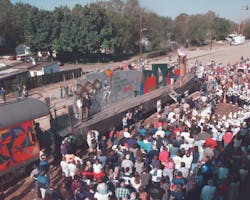
1. The Olympic Cauldron Car pauses for trackside ceremonies in Boise, Idaho on May 9. A hydraulic drive raises the torch (as it is here) for all to see when the car is stationary and lowers to torch for safety and to keep it from being extinguished by wind when the car is in motion.
An unusual aspect of the cauldron car is a shield of air surrounding the flame. This shield protects the flame from winds by directing a strong current of air upward and dramatically reduces the effects of crosswinds or air rushing by the flame generated by the train’s motion.
Fans mounted below the cauldron push air upward at nearly 150 ft/sec through vents positioned around the circumference of the cauldron. Vinton Wolfe, senior research engineer at Atlanta Gas Light Co., designed and constructed a prototype to test the concept. Using a scaled-down model on a test track, the air shield was able to protect the flame at speeds exceeding 65 mph. This was deemed satisfactory, especially because the 42-in. diameter cauldron on the Cauldron Car would be less likely to be blown out than the smaller flame on the model.
Advance Hydraulics, Milwaukee, was commissioned to design and build the hydraulic system for the Cauldron Car. The basic requirements seemed simple enough: provide a hydraulic system to raise and lower the cauldron from a control panel mounted either on the Cauldron Car itself or from a remote location in an adjacent car. Cycle time to fully raise the cauldron from a lowered position had to be 30 seconds or less. However, addressing details of the design requirements proved the biggest challenge, because much of the Cauldron Car was still being developed, and design parameters were subject to change.
The cylinder for raising and lowering the cauldron required a hollow rod for routing fuel and air lines (for the air shield) to the cauldron. This meant the cylinder would have to be custom designed and built. Because much of the Cauldron Car was still in a concept stage, hand-drawn sketches were all Advance Hydraulics had to work from. Much of the car had not actually been constructed, so design requirements were not finalized. Therefore, Advance Hydraulics had to design the system with generous flow, pressure, and stroke capabilities. Working with a worst-case scenario, they could throttle back flow, pressure, and stroke to match actual requirements. One more minor detail: the project had to be completed and tested in three weeks.
Hydraulic System Design, Operation
Layout of main hydraulic components is shown in the schematic (Fig. 2). Power is delivered to the hydraulic system at 29 gpm at up to 900 psi by a Hydreco fixed-displacement gear pump, which is manufactured by Magna-Pow’r Inc., Franklin Park, Ill. Main directional-control valve A has an open-center configuration that dumps fluid to tank at low pressure when the valve is centered. This configuration serves as an energy-saving alternative to blocking flow from the pump and dumping it to tank over the high-pressure relief valve. Due to space constraints, all directional- and flow-control valves, manufactured by Northman USA Inc., are stack mounted on the power unit.
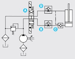
2. Schematic shows major components of hydraulic system for raising and lowering cauldron bearing Olympic flame.
Raising the cauldron — Shifting directional-control valve A downward routes fluid from the pump into the lower fluid line. Fluid encounters little resistance as it flows into the cap end of the cylinder through check valves B and C. However, check valve D forces fluid flowing out of the rod end through the flow-control orifice, which regulates extension speed. After passing through this orifice, fluid has an open path back to tank.
Lowering the cauldron — Shifting directional-control valve A upward routes fluid in the upper line around flow-control orifice D through the check valve. This provides a path at full flow into the rod end of the cylinder. However, pilot-operated check valve C, in the lower fluid line, prevents fluid from flowing out of the cap end of the cylinder. This keeps the piston rod from retracting unless the upper fluid line is pressurized. Pressure in the upper fluid line builds due to the blockage offered by valve C, but valve C opens when enough pilot pressure has developed in the upper fluid line. This routes fluid from the cap end of the cylinder through flow-control orifice B in the lower fluid line. This orifice offers enough resistance to keep pilot pressure high enough to prevent valve C from closing. Once it has passed though the orifice in the lower line, fluid has an open path back to tank.
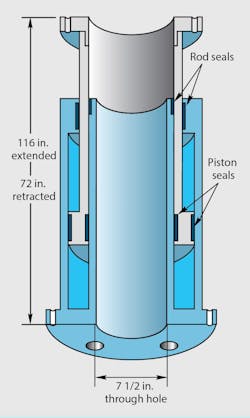
3. Sectional view shows internal workings of a hollow-rod cylinder that had to be designed, constructed, and tested within a 3-week production schedule.
The cylinder itself (Fig. 3), has a 7½-in. through-hole to accommodate service lines supplying the cauldron itself. Limit switches provide signals to the controller to indicate when the piston rod has extended or retracted to its final position. This simplifies control by stopping the cylinder automatically, so an operator simply has to push a raise or lower button to place the cauldron in the desired position.

