Think First, Then Troubleshoot — Chapter 12: System Test for Flow-control Valves
Loads frequently vary as actuators cycle, creating variable pressure drops that result in unwanted actuator speed variations. Pressure-compensated flow control valves maintain a constant fluid flow through a variable orifice in the valve. The valve’s compensator spool will move toward an open or closed position in response to work-load changes. A pressure-compensated flow control valve is installed to ensure a constant pressure drop over the valve’s variable orifice, or throttle. The setting of the variable orifice determines flow through the valve. The compensator controls the pressure at the variable orifice, resulting in smoother, constant flow through the valve regardless of load changes on the actuator.
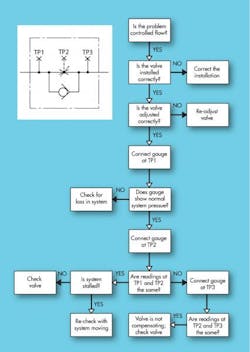
Troubleshooting flow-control valves can be made easier by installing pressure gauges at inlet port TP1, outlet port TP2, and internal pressure chamber TP3, Figure 15. Typical problems encountered and remedial actions include:
A pressure-compensated flow control valve combines a pressure-reducing valve and a needle valve in the same housing. Instead of being ported to atmosphere, the load-sensing line of the pressure-reducing element is connected to load pressure between the needle valve and the actuator. There are two types of pressure-compensated flow control valves: bypass and restrictor. The restrictor type is most commonly used because it can be specified for meter-in, meter-out, and bleed-off circuits. Bypass flow control valves are not discussed in this article.
System circuit designers must make sure that there will be a pressure differential between system pressure and actuator working pressure. You can achieve this by sizing the actuator so that load pressure is lower than system pressure. The level of pressure drop required to maintain good compensator response varies with valve designs. Typical pressure drops range between 75 and 175 psi. Erratic actuator movement or changes in set speed indicate improper valve performance or inadequate pressure differential.
Inadequate pressure differential between main system pressure and actuator working pressure — Check for adequate pressure differential using gauges at TP1 and TP2. Follow the valve manufacturer’s recommendations.
Sticking compensator spool — Check pressure differential between the inner pressure chamber and valve outlet pressure, using gauges a TP3 and TP2, respectively. The pressure differential should approximate the compensator spool spring load. Fluid contamination and/or spool body scoring can cause erratic spool movement or hand-up. Either can affect the constant pressure drop needed across the throttle orifice.
Worn or contaminated return-flow check valve — Problems with free-flow return check valves can contribute to faulty operation. Inspect for worn seat-poppet or presence of contaminants. Either could allow oil flow through the check valve in the direction of controlled flow. An open check valve could cause identical pressure gauge readings at TP1 and TP2.
Drain line in flow control valve not vented to atmosphere – Needed in valves requiring draining at the top of the throttle to get rid of internal leakage. If the drain port is not ported to atmosphere, the valve will rupture in the area of the adjusting handle.
In summary, fluid contamination, worn internal parts, and the absence of good circuit design will cause pressure-compensated flow control valves to malfunction.
About the Author
Alan Hitchcox Blog
Editor in Chief
Alan joined Hydraulics & Pneumatics in 1987 with experience as a technical magazine editor and in industrial sales. He graduated with a BS in engineering technology from Franklin University and has also worked as a mechanic and service coordinator. He has taken technical courses in fluid power and electronic and digital control at the Milwaukee School of Engineering and the University of Wisconsin and has served on numerous industry committees.

Leaders relevant to this article:

