Evacuating air from a closed volume develops a pressure differential between the volume and the surrounding atmosphere. If this closed volume is bound by the surface of a vacuum cup and a work piece, atmospheric pressure will press the two objects together. The amount of holding force depends on the surface area shared by the two objects, and the vacuum level. In an industrial vacuum system, a pump or generator removes air from a system to create a pressure differential.
Because it’s impossible to remove all air molecules from a container, a perfect vacuum cannot be achieved. Of course, removing more air increases the pressure differential and strengthens the potential vacuum force.
The pressure differential between the evacuated volume and surrounding atmosphere determines vacuum level. Several units of measure can be used—for instance, most refer to the height of a column of mercury, usually in inches of mercury (in.-Hg) or millimeters of mercury (mm-Hg). The common metric unit for vacuum measurement is the millibar, or mbar. Other pressure units sometimes used to express vacuum include the interrelated units of atmospheres, or “torr,” and microns.
One standard atmosphere equals roughly 14.7 psi (29.92 in.-Hg). Any fraction of an atmosphere is a partial vacuum and equates with negative gauge pressure. A torr, defined as 1/760 of an atmosphere, can also be thought of as 1 mm-Hg, where 760 mm-Hg equals 29.92 in.-Hg. Even smaller is the micron, defined as 0.001 torr. However, these units are used most often when dealing with near-perfect vacuums, usually under laboratory conditions, and seldom in fluid-power applications.
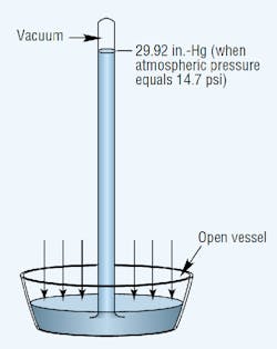
Atmospheric pressure is measured with a barometer. A barometer consists of an evacuated vertical tube with its top end closed and bottom end resting in a container of mercury that’s open to the atmosphere. The pressure exerted by the atmosphere acts on the exposed surface of the liquid to force mercury up into the tube. Sea-level atmospheric pressure will support a mercury column generally not more than 29.92 in. high. Thus, the standard for atmospheric pressure at sea level is 29.92 in.-Hg, which translates to an absolute pressure (psia) of 14.69 psia.
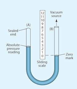
The two basic reference points in all of these measurements are standard atmospheric pressure and a perfect vacuum. At atmospheric pressure, the value 0 in.-Hg equals roughly14.7 psia. At the opposite reference point, 0 psia, otherwise known as a perfect vacuum (if it could be attained), would have a value equal to the other extreme of its range, 29.92 in.-Hg. However, calculating work forces or changes in vacuum-system volume requires conversions to psia or negative gauge pressure (psig).
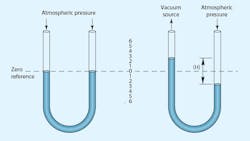
Most pressure-gauge dials assign the value of zero to atmospheric pressure. Vacuum measurements must, therefore, be less than zero. Negative gauge pressure generally is defined as the difference between a given system vacuum and atmospheric pressure.
Industrial vacuum systems
Vacuums fall into three ranges:
• Rough (or coarse), up to 28 in.-Hg
• Middle (or fine), up to one micron
• High, greater than one micron
Almost all industrial vacuum systems are rough. In fact, most lifting and work-holding applications operate at vacuum levels of only 12 to 18 in.-Hg. That’s because, typically, it’s more economical to increase the lifting or holding force by increasing the contact area between the work piece and vacuum cup than it is to pull a higher vacuum and use the same contact area.
Middle vacuum handles process applications, such as molecular distillation, freeze drying, degassing, and coating operations. High vacuums are used in laboratory instruments, such as electron microscopes, mass spectrometers, and particle accelerators.
A typical vacuum system consists of a vacuum source (mechanical pump or vacuum generator), delivery lines, fittings, and various control valves, switches, filters, and protective devices. Leakage prevention is especially important with vacuum systems, because even the tiniest of leaks can greatly diminish performance and efficiency. It’s important to only use tubing designed for vacuum service. Otherwise, the walls of the tubing could collapse under a vacuum and block flow. Also, vacuum lines should be as short and narrow as is practical to limit the volume of air that must be evacuated.
Work-holding applications should only use the vacuum pump to reach the required vacuum level. Once the work piece comes in contact with the vacuum cup and achieves the required vacuum, de-energizing a normally closed valve will hold the vacuum indefinitely—provided there are no leaks. Holding a vacuum in this manner consumes no energy and avoids having to operate the vacuum pump continuously.
Companies also offer proprietary devices, such as vacuum cups with integral valves and valves that terminate flow from a cup that exhibits excessive leakage. This valve is designed to avoid false-alarm shutoff when holding porous work pieces (such as cardboard), yet prevent a leak at one vacuum cup from reducing vacuum at an adjacent cup.
Vacuum sources
A mechanical vacuum pump may be thought of as a compressor that operates with its intake below atmospheric pressure and the discharge at atmospheric pressure. Compressors and vacuum pumps have identical pumping mechanisms. The vacuum pump, however, is simply piped to withdraw air from a closed container and exhaust to atmosphere, while the compressor does the opposite.
Although compressors and vacuum pumps share many similarities, two significant differences between them must be considered in system design. The maximum change in pressure produced by a vacuum pump is limited; it can never be higher than atmospheric pressure. Plus, increasing vacuum causes a continuous drop in the volume of air passing through the pump. Therefore, the pump itself must absorb virtually all generated heat. A rising vacuum level means less air is present to carry away the generated heat, so the pump must absorb more of that heat.
Many machines that require vacuum also use compressed air. In addition, if vacuum is required only intermittently, the already-available compressed air can be used to generate vacuum through a vacuum generator, also known as a vacuum ejector.
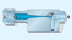
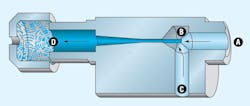
Vacuum generators operate on the venturi principle. Filtered, non-lubricated compressed air enters through inlet A. A diffuser orifice (nozzle), B, causes the air stream to increase in velocity, thereby lowering its pressure and subsequently creating a vacuum in channel C. The air stream exhausts to atmosphere through muffler D.
Due to the compact and lightweight nature of vacuum generators, they often can be mounted at or near the point of use. They’re inexpensive, and because they have no moving parts, maintenance pales in comparison with mechanical vacuum pumps. They don’t need a prime mover because they generate vacuum by tapping into an existing compressed air system. However, retrofitting the generator into a machine may require increasing the capacity of the existing pneumatic system. Heat generation, often a limiting factor with mechanical vacuum pumps, is of little concern with vacuum generators.
Vacuum source selection
To calculate a system's vacuum needs, consider all work devices to be driven. The devices’ working vacuum can be determined by calculations based on handbook formulas, theoretical data, catalog information, performance curves, or tests made with prototype systems. After determining the vacuum requirement, the search can begin for pumps that accommodate application needs.
The maximum vacuum rating for a pump, which is commonly expressed for either continuous or intermittent duty cycles, can be obtained from manufacturers. Because the maximum theoretical vacuum at sea level is 29.92 in.-Hg, capabilities are based on, and compared to, this theoretical value.
How long to reach maximum vacuum?
In general, a small capacity source and a large capacity source with equal maximum vacuum capabilities will both produce the same vacuum. It just takes longer with the smaller pump. How much longer depends on the capacity of the source and the size of the system. Simply dividing system volume by open capacity won't produce the proper answer, though.
The higher the vacuum, the fewer air molecules remain in the closed volume. Therefore, fewer molecules can be removed per unit of time. As a result, there’s a logarithmic relationship when approaching a perfect vacuum. The time required to pump a system down to a certain vacuum level can be approximated using the following formula:
t = V × n ÷ q
where t is time (minutes);
V is system volume (ft3);
q is flow capacity (cfm); and
n is a constant for the application.
For exact applications, n can be determined by using a natural logarithm. For most purposes, the following following values for n can be used:
n = 1 for vacuum to 15 in.-Hg
n = 2 for vacuum >15 but ≤ 22.5 in.-Hg.
n = 3 for vacuum ≥ 22.5 and up to 26 in.-Hg
One further complication—capacity in the equation is not the open capacity (capacity at atmospheric pressure) usually cataloged by manufacturers. Instead, it represents the average capacity as system pressure drops to the final vacuum level. This value isn’t readily available, but can be approximated from manufacturers' performance curves. These curves plot capacity at various vacuum levels.
To mesh these curves with the equation, simply substitute values in the equation using capacity readings from the curve at various vacuum levels at 5-in.-Hg increments, up to the desired level. Then total these times.
Finally, note that this pump-down time is based on all system components operating at optimum levels. A 25% additional time allowance is recommended to compensate for system inefficiencies and leakage.
About the Author

Leaders relevant to this article:
