Load interactions in the full series system
In continuing the discussion from last month, the partial series connection derives its name from the fact that the return flow from the load actuator does not recombine with the upstream bypass flow before supplying the downstream functions. Instead, the return flow from each 4-way valve section is sent directly to tank. Only the bypass flow from upstream functions is used to power the downstream functions.
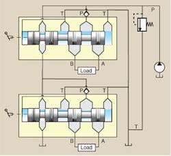
The connections are illustrated in the cutaway diagram of Figure1. Notice how the bypass connection between sections connects through the transition check valve to the pressure port of the second section. An important feature of this valve type can be seen when you consider what happens if you fully shift the upstream spool: the upstream bypass flow is completely cut off, and there is no flow available to the downstream functions. Simultaneous operation of more than one function is limited to those conditions when only partial shifting of the upstream functions occurs.
No intensification
Unlike the full series configuration, neither pressure nor flow intensification can occur. However, regardless of valve type, valve control is an energy consuming control method, and partial shifting can result in high power consumption because the 4-way lands are partially shut off. When fully shifted, the throttling restrictions are less severe, and higher efficiency results — but only one function is active.
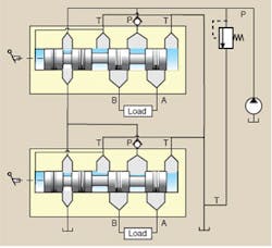
In the interest of completeness, the ISO conventional schematic is shown in Figure 2. In this figure, again, the partial series feature can be seen as the connection between each of the two 4-way return ports and the internal tank connection. Also, clearly shown, is the bypass connection that supplies fluid to all the downstream functions. Equally clearly, it shows how downstream flow is cut off in the event of full shift of an upstream function.
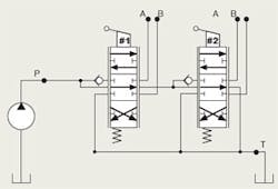
There is no simplified ISO schematic representation of the partial series valve stack, as was the case with the full series configuration. The simplified analytical schematic is helpful in visualizing the interactions when multiple functions are shifted. The circuit is shown under the condition that the 4-way sections are both shifted to extend their respective cylinders.
Load interactions
Load interactions exist, to be sure, when multiple functions are shifted. But, as already stated, the intensification possibilities are not present. Figure 3 shows the simplified analytical schematic for a 2-function, partial series connected directional control valve. It is helpful in visualizing the interactions in a 2-function valve stack.
The interactions are mostly those from flow sharing between the active functions affected by the relative loads in the two functions and the amount of shift in the active spools. That is, flow taken by one of the functions, obviously, cannot be used by the other. Also, if the function with a heavy load is shifted, and the other function (carrying a lighter load) is shifted while the first cylinder is in motion, a reduction in the pump pressure can result that can cause the heavily loaded cylinder to stop.
All the flow goes to the lightly loaded function. This scenario is most likely to occur when a large disparity exists between loads on the two cylinders — and the lightly loaded cylinder is upstream of the heavily loaded one. It is worth emphasizing that the transition check valves are vital in preventing the heavily loaded cylinder from settling in the reverse direction. They cause it simply to stop moving.
When the heavily loaded cylinder is connected to the upstream function, some degree of simultaneous operation is possible. In this scenario, the heavily loaded function upstream is shifted first, but not fully shifted. This means the upstream bypass orifice is partially open, so some of the pump flow is available to the second section. Shifting the second (downstream) function will result in routing fluid to the second cylinder. If its load is relatively light, some motion is possible, albeit limited, compared to not having the upstream function shifted at all.
If the downstream load is relatively heavy, the upstream pressure will be insufficient to crack open the downstream transition check valve. Therefore, the heavier downstream load will not start. In this case, the downstream function will be acting as a sort of “auxiliary bypass.”
To elaborate, suppose the downstream spool is fully shifted so its bypass orifice is closed. Now, all the pump flow must enter the upstream cylinder, so it will increase in speed. The pump pressure will also increase. Operator skill is essential in achieving well-coordinated simultaneous motion in two cylinders with this valve type. Also, the relative degree of cylinder loading has to cooperate, but that is not always possible.
Whatever scenario is imagined, we can predict many of the consequences. We can write the equations dictated by Kirchoff ’s laws of hydraulic circuits and calculate the pressures, flows, and actuators’ speeds.
I encourage readers to explore other combination scenarios, such as operating conditions that result when one cylinder reaches full extension. And by all means, look back at recent back issues to compare the full series connection to the partial series connection. The variety of diagrams presented should help in the explorations.
Next month we’ll continue exploring valves used in mobile equipment by examining the parallel connected open-center directional control valve stack.
Jack L. Johnson, E., is an electrohydraulics specialist and president of IDAS Engineering Inc., Milwaukee. For more information, contact him at (414) 355-0152 or e-mail [email protected].


