Hydraulic-Electric Analogies: Motors and Generators, Part 6
This file type includes high resolution graphics and schematics when applicable.
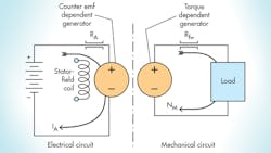
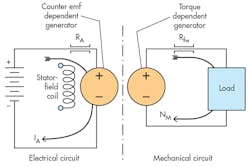
Looking at an analytical schematic of a generic dc electric motor (Fig. 15, left), we see the battery power supply, stator field coil, an electrical resistance (RA), and the electrical circuit account for the electrical resistance in the armature circuit. A “dependent generator” in the electrical portion accounts for the back electromotive force, or emf (speed voltage), caused by the rotor coil(s) spinning within the electromagnetic soup into which it’s immersed. The spinning coils move in the magnetic field and generate a dependent voltage.
What is meant by a dependent generator, though? It is a circuit concept created by electrical circuit analysts, but later developments show that the concept extends analogously and perfectly to mechanical and hydraulic systems as well. All it means is that the output of some type of generator depends on something going on in another part of the circuit.
In the case at hand, the counter emf generator in Figure 15 depends on the speed (labeled NM on the right) in the mechanical part of the circuit. Simply interpreted, it means that the faster the motor shaft turns, the higher the counter emf. This concept will be shown later to apply to hydraulic pumps and motors. The use of dependent generators is actually a schematic construction of the bilateral operation discussed in “Hydraulic-Electric Analogies: Torque-Speed Behavior, Part 4," plus the dependent generators greatly simplify circuit analysis.
The right side of Figure 15 shows the mechanical-output equivalent circuit as a “dependent” torque generator and output rotational speed (NM), the speed that affects the motor’s counter emf. The dependent generator accounts for the torque that comes from the current-carrying rotor coil. That is, its torque depends on the amount of armature current (IA).
Recall that voltage, pressure, torque, and force are all analogous concepts, as are current, flow, linear speed, and rotational speed. Analytical schematics and their dependent generators allow us to keep the various elements separate but connect them together when they interact—such as speed and voltage, or torque and current, in the motor.
Armatures and Rotors
One dc-motor-related term that hasn’t been discussed yet is “armature.” Traditionally, the term armature was meant to be that part of the machine to which electrical input power is applied. Some of the earliest motors of Edison’s day were dc motors and the power is applied to the rotating member of the dc motor, or rotor. Clearly, the traditional definition makes the rotor and armature the same device.
Using that same traditional definition for ac motors, the armature consists of the stationary field windings because they are the elements to which the external ac power is applied. In addition, the motor’s torque arises from them.
At this point, it also must be acknowledged that the term armature has been so universally corrupted that it now means “the movable member of an electromechanical machine.” That corruption will be accepted as “neo-gospel” and used from time to time in this discussion. For example, it is now accepted that the armature of a proportional solenoid is the totally passive, iron movable member. This, too, is the case with the servo valve’s torque motor, where the armature is the solid-iron rotating member, and not the coil. And so it goes.
Series-Connected DC Motors
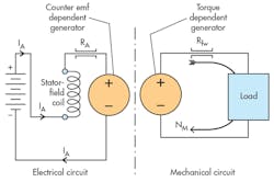
The “series-connected” dc motor refers to the connection of the stator field, whereby the current powering the armature is the same current that goes through the stator field (Fig. 16). This produces a motor configuration that will run at very high speed when there’s little mechanical load on the shaft and slow down significantly with increased load.
To understand the relationship between stator-field magnetic flux and the speed, recall that the motor will accelerate until the counter emf equals (or nearly equals) the supply voltage, i.e., the battery voltage in the figure. When power is first applied, the motor shaft is not turning. Counter emf is nil; therefore, the current jumps to a high value. The high current causes a large starting torque, which accelerates the motor. However, as it accelerates, the counter emf increases, reducing the armature current (IA). But the reduction in current reduces field flux, and in turn the motor speeds up to generate a high counter emf. This causes a further reduction in flux, which requires yet more speed, and on and on. At the same time, though, the reduced flux lowers the torque, reducing the acceleration, and on and on goes that cycle.
In the end, an equilibrium arrives wherein the motor stops accelerating at some finite armature current and some finite shaft speed. This motor is perfectly analogous to the pressure-compensated motor, whose displacement increases with more pressure. The result is a motor with high speed at low pressure (load) and low speed at high pressure (load), just like the series-connected motor.
Shunt- or Parallel-Connected Motors
Shunt connection and parallel connection are synonymous terms. In the shunt-connected motor, the reference is to the field-winding connection relative to the armature connection.
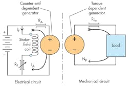
Figure 17 shows an analytical schematic of the shunt-connected dc motor. The circuit is equipped with a variable resistance (RF) that can be used to adjust the field current. Changes in field current produce commensurate changes in magnetic field strength, which, in turn, can be used to change the motor’s speed at a given output load condition. In this respect, the behavior of the speed is the same as in the series connection—at least in principle. That is, a decrease in RF will cause a greater current, which will slow the motor down at constant shaft loading. The greater field strength means that the counter emf will be nearly the battery voltage at a lower speed.
DC Generators
Essentially, dc generators are the same machines as dc motors. The only significant difference is that the motor has electrical power entering the armature circuit, which produces mechanical power that issues from the output shaft, while the generator receives mechanical power as an input and generates an output voltage and current.
The analytical schematics are also identical in their essential parts, consisting of two dependent generators—one for torque and one for voltage. Dependent generators are the circuit elements that make both generators and motors bilateral machines. That is, a generator can act as a motor under the immediate circumstances, and a motor can act as a generator under different circumstances. And the input knows what is happening at the output and vice versa.
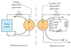
Figure 18, which is an analytical schematic of a dc generator, offers another opportunity to look at the dependent generator concept in further detail. The dependent voltage in the electrical output side of the circuit represents the speed voltage caused by the armature windings spinning in the field flux. The voltage depends on the field strength and the speed (NP) that exists in the mechanical input side of the circuit.
Generally speaking, generators are purchased for the voltage generator. The torque generator “comes along with the territory,” so to speak. That is, it represents the counter torque caused by the current in the electrical output side of the circuit. As the load demands more current (not shown in the figure), more torque is required from the prime mover to keep the shaft spinning. In this way, the prime mover “knows” there’s an increased load. Furthermore, the analytical schematic is consistent with the need for energy-conservation theory.
The shunt-connected generator is perfectly analogous to the variable-displacement pump. If the generator turns at some constant speed (value is not important) and the stator field current is increased, more voltage will be generated and more current will be delivered to the load. In the variable-displacement hydraulic pump, which also turns at some constant speed, an increase in displacement will result in a greater output flow along with a likely rise in pump output pressure.
