Optimal design for motor speed control
Suppose we must power a conveyor with a hydraulic motorfor transporting agrregate. Conveyor speed must be variable, but a dedicated pump is not available. therefore, we must control motor speed with a proportional valve. We can tap into a hydraulic power unit with a pressure-compensated pump set to deliver 1800 psi. The conveyor motor must deliver 2500 lb-in. of torque at 2400 rpm into a speed reducer that drives the conveyor's main pulley. Our task, then, is to determine the optimal size of the motor and valve to deliver the required torque and speed.
Calculating valve coefficient
Our first step is to calculate the required motor displacement. Because the application calls for a high-speed motor, the mechanical efficiency at stall can be expected to be about 80%, and the leakage will cause the valve pressure drop to be about 5% of the supply pressure — 90 psid. Without delving into the derivation here, we calculations reveal the displacement to be 17.22 in.3/rev.*
To keep costs low, we will specify a gear motor, so we expect volumetric efficiency to be about 88% and the mechanical efficiency to be in the 90% range. This information, combined with the motor displacement,can be used to calculate the valve coefficient. For this example, the valve coefficient is 28.33, but to illustrate the complexity of the calculations, the units for the valve coefficient are in.3/ (sec psid1/2). But we're not finished; the valve coefficient now has to be converted to rated flow of the valve. Because we will be using a proportional valve, the rated pressure, according to ISO 10770-1, is 145 psid, or, 1 MPa. The rated flow of a valve with a total coefficient of 28.33 is calculated as 88.6 gpm from the standard orifice equation.
Specifying components
At this point we must find a real valve and a real motor, knowing that the optimally sized valve will be rated at 88.6 gpm and the optimally sized motor will have a displacement of 17.22 in.3/ rev. A motor with these exact values will not be available off the shelf, so the selection must be a compromise. Specific components must be evaluated to ensure that the compromised values will meet the design targets of motor speed and displacement under load. At validation time, we will know all the motor and valve parameters.
If a slightly larger than optimal valve and motor are selected, and the actual efficiencies are at least as good as those we calculated, the selected hardware will always meet the design goals. Many times, one component can be sized slightly smaller and the other slightly larger, and the combination can work as well. However, if both components are undersized, not enough power will be delivered to the load to simultaneously meet speed and torque requirements.
This is a generic discussion, so when evaluating commercially available valves and motors, we will avoid covering specific brand products. Instead, assume we have found a valve and motor sized the same as our calculations.
Flow requirements
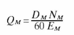
Once the motor and valve have been sized, the flow requirements of the power unit can be calculated using the well-known relationship involving displacement, speed and volumetric efficiency:
where QMis motor flow, in.3/ sec
DMis motor displacement, in.3/ sec
NMis motor speed, rpm
EMis motor efficiency, %
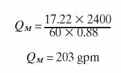
For the example problem, we are interested in the flow at the design point, so:
Note that the proportional valve is rated at only 88 gpm but is required to operate at 203 gpm — the operating flow of the valve is more than double its rated flow. This could be a problem, depending on what proportional valve is selected.
All valves are subject to internal flow forces that act to close the spool when pressure drop and flow are high. If the method for positioning the valve spool cannot generate enough force to hold the spool at or close to its commanded position against the flow forces, maintaining speed will be impossible, especially when the load is light.
On the other hand, a valve of this size cannot be direct acting. Rather, it must be pilot operated, and hydraulic pilot operators usually are capable of developing much more force than flow can. In any event, the valve manufacturer must be consulted to assess the suitability of the selected valve.
If the load is removed, the motor will accelerate to the slew speed, also called the no-load speed. That slew speed can be determined by calculating shaft speed and imposing no-load conditions on the motor. The problem is, we need to know the no-load torque and the mechanical efficiency under no-or low-load conditions. The solution is complicated by the fact that mechanical efficiency is a very nonlinear function of load and speed. However, an intuitive means exists for estimating some values.
In our conveyor application, the no-load condition occurs when no aggregate is on the belt. Therefore, the motor would only have to overcome its own internal friction, the friction in the gear box, and the friction in the empty conveyor. In other words, more load is on the motor than if the motor shaft were completely free. Therefore, it may be easier to estimate the pressure required to propel the empty conveyor than it is to get good figures for the no-load torque and mechanical efficiency.
In this application, it would be reasonable to expect the pressure required to move the empty conveyor to be as much as 20% or 30% of supply pressure. For our example problem, we will assume it takes about 400 psid pressure drop across the motor to drive the empty conveyor. We also need to know the volumetric efficiency of the motor under these low-load conditions. The motor approaches 100% volumetric efficiency when it has no load, so it is reasonable to set it to 100%.
If the motor must operate with full system pressure, 1800 psi, no load on the conveyor, and a full open control valve, then the power unit has to be capable of delivering 275 gpm in order to sustain the 3693 rpm.
A word from the authorElectrohydraulic servo systems are at the heart of all modern hydraulic motion control systems, but few engineers really have a command of this exciting technology. In our continuing quest to disseminate electrohydraulic technology, we at IDAS Engineering Inc. have prepared a 55-minute educational video on a servomechanism. It's on a CD, and will play directly on your Windows-based computer. This animated video clearly and graphically describes the dynamic actions that take place when using electrohydraulic feedback control. You can see the command changing and immediately observe the effects on the output of a cylinder. You can even track the control valve current. And perhaps best of all, it is non-mathematical. And what happens to the error in the servo system? You'll be able to examine that, too, and for a small fraction of the time and money I have invested in developing my career around these machines. This video offers you the quickest and least painful way to gain valuable insights into the operation of feedback control systems as they are applied to electrohydraulic servomechanisms.Colorful motion graphics illustrate the more subtle nuances, such as saturation and timing of valve spool motion. The video comes with a A 60 question exam, designed to challenge your knowledge of not only concepts covered in the video, but general knowledge of hydraulic systems. Pretty soon, everything is going to be servo controlled. Only the technically qualified will be able to compete in this exploding technical field. So order yours right away to get a running start on this growing motion control technology. Purchase both for only $43.00 for the H&P Bookstore. Just click here and scroll down to Animated Video CD: Introduction to Electrohydraulic Servo Systems to lean more. |


