A Checklist for Sizing Hydraulic Filters
To get the best performance out of a hydraulic system, it is essential that it have proper filtration. Choosing the right type of filter and sizing it properly could be the difference between a smooth running, long lasting hydraulic subsystem and one that performs poorly and is often down for maintenance.
But selecting the proper filter is not a simple task for designers or operators who must replace old or damaged filters. Even if a maintenance team is replacing a damaged filter with one just like it, the team should ensure it is the right filter for getting the job done efficiently and effectively.
To get the right filter, engineers and designers need to know and understand hydraulics and the application, including its performance requirements.
READ MORE: How And Why To Monitor Hydraulic Filter Condition
There are a dozen questions designers and operators should consider before that will help designers get to know the application and choose just the right filter.
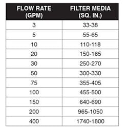
What is the pump’s flow rate? Knowing the pump’s flow rate for the fluid will determine the filter media’s surface area. The table below shows an approximate filter size (in square inch of filter media) and the acceptable flow rates.
What is the pipe size? Flow rate and pipe size go hand in hand. The filter must be properly sized to keep the pressure drop compatible with the fluid passing through it. A pump putting out 50 gpm, for example, will create less pressure drop when going through a 3-in. npt (American National Standard Taper Pipe Thread) pipe than through a 1-in. npt pipe. The pipe size will help focus filter selection. A general reference chart below relates pipe size to flow rate.

Typically flow velocities in hydraulic subsystems should be high enough to ensure the subsystems run smoothly and efficiently. In pump suction lines, flows should be travelling roughly 2-4 ft. per second (fps); in pressure lines, 10-25 fps is the range for fluid velocities; and for return lines, the figure is 5-10 fps.
What is the working system pressure? The answer to this question will let designers choose a filter that will withstand that anticipated pressure. If the filter can’t and it collapses, it will likely lose its integrity, break down, damage the entire hydraulic subsystem and lead to a possible breakdown. To make matters worse, when a filter collapses, fragments of epoxy or filter media are injected into the flow stream and can damage downstream equipment.
RELATED
Understanding Filtration Specifications
5 Filtration Technologies for Hydraulic Systems
Avoiding Lubricant Contamination
What is the fluid? Is it standard hydraulic fluid? Is it a petroleum-based product compatible with the equipment? These answers will let designers and operators know if the fluid is compatible with all system components as well as filters. If it is not, be prepared for serious system damage or destruction.
For example, if phosphate ester is the process fluid, polyester, nylon and stainless steel filter media are fine, but polypropylene is unacceptable. Standard hydraulic oils are compatible with filter media such as cellulose, polyester, polypropylene, stainless steel and most other types of media. The point is to ensure that the process fluid, filter media and seal material are all compatible. If there are any compatibility issues in any area, there will be leaks and major contamination problems.
What is the fluid’s viscosity? Standard hydraulic fluid has a viscosity of 150-200 SUS (Saybolt Universal Seconds, the time [in seconds] for 60 ml of oil to flow through a standard orifice at a given temperature). Any fluid with a higher viscosity is thicker than standard hydraulic fluid. Fluids with higher viscosities create higher pressure drops as they flow through the system, especially during cold weather start-ups. Designers and operators should be aware that allowable initial pressure drops vary widely from component to component and so they should know system requirements for pressure and ensure they will be met.
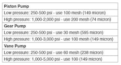
What type of pump is being used? Is it a piston, gear, vane or other type of pump? This is important to know when installing a new or replacement suction strainer. Suction strainers keep contaminants out of the pump, the most important component in a hydraulic subsystem. Different types of pumps sometimes require more protection. The chart below provides general guidelines for adequately protecting hydraulic pumps.
What mesh or micron should be used? To completely size a filter, knowing the filtration level is critical to efficiency. Suction lines should be no finer than 200 mesh (74 micron). Having filtration that is too fine on the suction side can cause pump cavitation. (See the table above for guidelines on filter mesh.)
Typically, the pressure line has the finest filtration in the system because it is the most critical. So, the pressure line filter mesh could be in the sub-micron area, depending on the application. The return line should be anywhere from 5-74 microns, again depending on the application. This is an area that should be looked at closely because applications, requirements and operational scenarios vary so much.
What type of filter is required? If it is a suction strainer, is it in-tank or in-line? Is it a replacement filter for an existing housing or does it also have a cartridge that must be replaced? Is the filter media wire cloth, cellulose or synthetic? If it’s a synthetic material, has it been performing properly?
Will the system operate continuously, intermittently or infrequently? If a system operates continuously, possibly working three shifts per day, the filter chosen must be able to endure the rigors of that operational pace. If the filter will be used in a subsystem that operates only once in a while, a less costly filter may do the job. The worst possible occurrence is machine breakdown because the filter installed couldn’t withstand the operation.
What is the system operating temperature? A hydraulic subsystem’s standard operating temperature is usually around 100°F. If the temperature runs hotter than that, the system should be kept cool. Too hot a system destroys seals, causes leaks and breaks down the fluid. Either a cooler should be installed or high-temperature seals made of Buna, Teflon or Viton should be used.
Is the system mounted inside or outside? Moisture is the second most damaging contaminant in any hydraulic subsystem. With outdoor hydraulic subsystems, exposure to rain, snow and humidity gives water a good chance of getting inside them. To prevent this, adding hygroscopic breathers can keep water out. Even in some indoor systems, depending on the local weather, moisture can cause problems. It may be necessary to use stainless steel filters with housings to prevent corrosion. If unsure if the metal in the filter is stainless or plated steel, find out what the other components are made of as that may help determine which materials should be used.

What about the air that gets into the reservoir? The tank breather is an area of hydraulic subsystems which seems to be neglected and not serviced as often as it should. As reservoir fluid levels rise and fall, atmospheric air enters and is expelled. The air carries both particles and moisture which contaminate the fluid held in the reservoir. To keep out these contaminants, a hygroscopic breather may be warranted.
Sizing this component is just as critical as any other filter. Air intake is measured in standard cubic feet per minute (scfm or just cfm). A general rule of thumb for sizing a tank breather is to divide the pump rating by 7.5 to get the cfm. For example, if the system is running at 100 gpm, then divide that by 7.5 to get 13.3 cfm. Most small breathers are rated for up to 35 cfm and are available with 3-5 micron filtration. Remember, it is permissible to oversize the air filter.
The answers to these questions will help designers and operators choose the best filter for a specific hydraulic subsystem. To protect the entire subsystem, all lines—suction, pressure, return and tank breather—must be adequately and appropriately filtered to keep it running smoothly and efficiently.
This article was written and contributed by Don Krause, general manager of business development at Ohio Fabricators Co. in Coshocton, Ohio.
This article is part of Power & Motion's Fundamentals of Fluid Power: Hydraulics ebook; download the full guide to learn about the latest technologies and design methods for developing modern hydraulic systems.
