This file type includes high-resolution graphics and schematics when applicable.
The subject of sealing with O-rings seems rudimentary to many designers. However, dealing with fixing seal leakage just one time can forever change the opinion of the designer. The purpose of this article is to offer a basic method for O-ring selection that will help prevent the time-consuming, costly, and potentially dangerous consequences of seal leakage due to improper choice of O-ring.
By definition, a seal is a device, or combination of devices, intended to prevent or drastically reduce the passage of a solid, liquid, vapor, or gas between two or more surfaces. Countless varieties of seals are in use, differing in both construction materials and geometry. One of the most widely used devices today is the O-ring.
The O-ring is a torus, or doughnut-shaped object, generally made from an elastomer that seals when compressed or deformed in a gland. The huge popularity of the O-ring seal dates back to 1939, when Niels A. Christensen was granted a patent for its design. In the 1940s and early 1950s, the O-ring evolved to become the standard seal for hydraulics in the military. The military established standard sizes and basic design guidelines that, with few exceptions, remain in use today.
In the mid-to-late 1950s, O-rings made the transition to the industrial sector. Soon, O-rings were designed into everything from farm equipment to automobiles, plumbing devices, even jewelry! Today, billions and billions of O-rings are used to seal virtually any device in every corner of the world.
The O-ring is considered such an elegantly simple, reliable, and cost-effective sealing solution for several reasons:
• O-rings are capable of bidirectional sealing
• O-rings are able to compensate for tolerance runout
• O-rings are reusable, within limits
• O-rings are resilient, thus eliminating re-tightening of bolts
• O-rings do not require any special installation tools or primers
• O-rings project a small sealing footprint, which enhances sealing properties
• The symmetry of the O-ring’s circular cross-section allows for sealing in any direction (radially, axially, or angularly)
• O-rings consist of a varied number of compounds that can resist virtually all aggressive chemicals and environmental application.
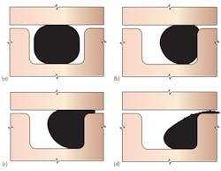
Even though O-rings have long been a widely used sealing solution, care must be taken to avoid some common pitfalls in selecting an O-ring for reliable service. Figure 1 illustrates an incorrectly specified O-ring placed under pressure. Proper planning eliminates problems, and O-ring selection is no exception. The following six-step guidelines should be followed systematically for every O-ring selection to minimize sealing problems downstream:
1. Determine the type of O-ring application you are working with.
2. Determine the media to be sealed.
3. Define the application time, temperature, and pressure envelope if applicable.
4. Determine the appropriate O-ring size based on the application type (i.e. face, radial, static, dynamic, etc.).
5. Check engineering calculations either manually or using available software programs.
6. Test design, if possible.
Several PC-based O-ring selection software packages are available that can assist the engineer. Regardless of the method of action, the above steps will prove reliable and complete. Let’s look at each step in a little more detail.
Static or Dynamic?
Sealing applications can be divided into two general categories: static and dynamic. In reality, the vast majority of sealing applications are primarily pseudo-static or pseudo-dynamic in nature. True static applications, in which there is no vibrational movement, are quite rare. To avoid problems at this point, the designer must be familiar with all aspects of the O-ring’s operating environment.
Vibrational movement, ozone attack, high ultraviolet exposure, intermittent use, constant use, etc., are all examples of factors that would influence the decision of whether the application is radial static or radial dynamic. Be sure to gain an understanding of these seemingly understated aspects of the design before proceeding to the next step.
What’s Your Fluid?
After establishing the O-ring application type, the next step is to determine the appropriate elastomer for the fluid to be sealed. The table compares various elastomers in terms of compatibility with different media. Often, the designer is required to balance the compatibility of a variety of media with a single O-ring seal. A common pitfall is not considering such ubiquitous things as cleaning solutions, maintenance programs, or alternate sources of fluids that have differing additive packages.
For elastomers to be deemed compatible with the media in question, the material must exhibit only minimal changes in properties (i.e., tensile strength, volume, elongation, and modulus) when exposed. Choosing an elastomer that is compatible with all media it comes in contact with is imperative for a successful O-ring selection.
Environmental Parameters
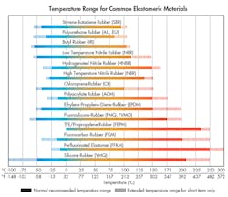
The next step in the selection process deals with the other environmental parameters of the application: temperature, pressure, and time. Figure 2 ranks the elastomers available today and their operating temperature capabilities. Based on the temperature range required of the design, an iterative process between steps 2 and 3 may be needed to choose the correct elastomer.
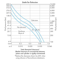
Figure 3 provides data on the pressure resistance of O-ring materials of differing hardness. If the pressure differential across the seal is very large, then it requires increased hardness. At this point in the selection, an iterative process between steps 1 and 3 may be required, depending on the specifics of the application. Fig. 3 offers a few guidelines in this regard. To avoid premature O-ring failures, the designer should establish some aggressive (but realistic) service-life targets.
Specific Sizes
Up to this point in the selection, the issues have involved the O-ring’s operating environment. Now is the time to decide what specific size O-ring is the best for the application. A set of standard O-rings based on Aerospace Standard 568 Rev. D is the starting point for any selection. In addition, a metric size standard (ISO 3601-1) will be appropriate for some applications.
Many handbooks and a few software packages also provide detailed tables when looking up the proper O-ring size for the hardware dimensions in question. This step is very easy, provided the hardware dimensions are standard. If not, then the designer must use the iterative process between steps 4 and 5.
Key Calculations
For every O-ring application, designers must concern themselves with three important design calculations: percent squeeze, compression percent stretch (if applicable), and volume/void ratio.
Again, for most standard hardware dimensions, these calculations are tabulated, so there’s no need for further calculations. However, if the hardware is unique, then these calculations will be required.
Design engineers should be willing to seek the assistance of an experienced O-ring designer or use one of the available selection software packages for this application. Improper calculation of the O-ring size will most certainly result in leakage.
Testing
In today’s harried engineering environment, the exercise of a test run or design-configuration run is somewhat of a luxury. Time constraints often do not allow verification of whether or not the selection is sound, and that no unanticipated situations will arise. This lends even more credence to having an organized approach to O-ring selection.
You may not be a certified O-ring expert just yet. However, by following these steps, you should have a framework from which to begin work on effective O-ring selections. Each step may have detail beyond the scope of this article, but should provide sufficient food for thought when approaching the simple, yet elegant, O-ring seal.
Dale Ashby is Vice President, Technology and Innovation, of Parker Hannifin’s Engineered Materials Group. For more information on O-rings, visit www.parkerorings.com, where you can download Parker’s free comprehensive O-Ring Handbook as a PDF or use their interactive O-ring eHandbook.
