50 years ago...Shock tests safer with electrically controlled circuit
From the November 1954 issue of Applied Hydraulics (the original title of H&P).
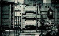
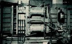
A reciprocating booster supplies high pressure to the cylinders, which clamp the shock tube's expansion and compression sections. An accumulator holds the clamping pressure.
Because of the need for remote stations and a positive, fail-safe system, designers of the Shock Tube Facility at the Massachusetts Institute for Technology use electrically actuated valves on a hydraulic locking and positioning circuit.
The shock tube generates shock waves in air or other gases and is used to study the effects of shock and blast waves, as well as the transient aerodynamic flow buildup on various structures. The shock tube is nearly 100 ft long and has an inside section measuring 8 24 in. At roughly a third of its length, the tube is divided into compression and expansion sections by a plastic diaphragm. The compression section is pumped up to a higher pressure than the expansion setting, and the diaphragm is punctured setting up a shock wave that proceeds down the expansion chamber.
Hydraulic power was selected to open and close the shock tube at both and diaphragm and instrument sections, clamp the tube sections closed at the diaphragm against an internal air pressure of 250 psi, and open and close a door at the end of the tube. Opening and closing the tube at the diaphragm section requires rolling the 30-ft-long fabricated steel sections that comprise the compression chamber, which altogether weigh about 5 tons. Clamping the compression section to the expansion section requires a force greater than 25 tons.
All the cylinders in the system are powered by oil from a variable volume vane pump that delivers a maximum 12 gpm to the system. At the diaphragm section, 6-in.-bore cylinders open, close, and clamp the sections. A 3:1 reciprocating booster is in the clamp circuit to boost the 700 psi, which the pump is set to develop, up to 2100 psi. A 1-gal accumulator was put in the circuit to maintain clamp pressure in case of pump shut off.
