Hydraulic Locks Protect Against Unplanned Moves and Dropped Loads

Hydraulic and pneumatic circuits contain load-holding and control valves; each holds an applied load in place and controls its rate of motion. When they operate as expected, they improve the circuit’s safety and control. These valves are the basic and the first line of load-holding safety—they are staples of circuit design.
But many critical safety and performance circuit requirements call for levels of safety these valves cannot provide on their own. Used alone, the valves and the rest of the hydraulic or pneumatic circuit are limited. Any failure or sticking in the valve, parallel check valves, hoses or fittings—or even seals leaking in an actuator—can cause unplanned and unsafe load movements if valves are the sole means of safety. Typically, these valves cannot be eliminated. Instead they must be supplemented to get the level of safety that is needed.
Locking Options
There are different options for supplemental mechanical locking and important parameters when choosing which to use: power needs; space available; operating pressure; operating environment; the need for locking in any location along the stroke, or only in fixed positions; and whether automatic or manual locking is best. These parameters determine the available options.
The most advanced locks hold the actuator rod anywhere along the stroke. They are “power removed” locks that instantly lock the rod when input pressure (power) is removed or lost. These locks are typically spring loaded or contain a second smaller hydraulic or pneumatic cylinder that is placed as a collar, or an installable “head,” on top of the main actuator-rod end cap. The lock fits around the rod and clamps against it to prevent movement.
These locks are inexpensive and common and are effective within their design limitations. They are intended to prevent failure, and with some designs, the load must be removed and the actuator moved in a specific direction to release the lock.
These off-the-shelf locks come in common rod sizes and can be hydraulic or pneumatic. They should be reliable and reusable and operate without too much maintenance or replacement requirements. They tend to be limited to cylinder pressures of 2,500 psi or less, so they cannot be used for high-load applications or with higher operating pressures.
With power removed, interference locks built into hydraulic cylinders deliver the highest level of safety performance. They meet the highest load demand and operating pressures, instantly locking at any position with no drift. They eliminate the need for other components in the power circuit that might cause a failure, including the cylinder seals and the fluid itself. They provide safety using just the integrated locking feature, the cylinder body and the rod. This means the cylinders have the fewest possible component fail points and failure modes that could cause uncontrolled and unplanned load movements or failures.
These designs are the strongest locking options in strength and will lock anywhere on the rod. They also provide zero backlash and high stiffness when required. They can have instant lock or unlock and there is no wear on components. As a positive lock, they lock when hydraulic pressure is removed, removing the risk of accidental pressure loss from any cause.
One locking system that meets most design criteria is the Bear-Loc from York Precision Machining & Hydraulic. It includes a supplementary section that attaches to the cylinder cap end. The system comes with a sleeve that creates an interference clamping/frictional lock; this holds the rod in any phase of the stroke when hydraulic pressure is removed. The sleeve has a fluid pressure lock and unlock port at the ends of the sleeve that are part of the hydraulic circuit.
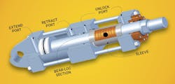
The Bear-Loc design uses the elastic expansion the of metal sleeve under pressure. When hydraulic pressure is applied, the sleeve expands radially, loosening the interference fit on the rod and making enough room for it to move with virtually no resistance. Removing the hydraulic pressure in any way makes the sleeve instantly engage its interference fit against the rod and clamp down on it. The sleeve is lined with a material that prevents the rod plating from degrading over the lifecycle of the rod.
The Bear-Loc instantly locks or unlocks simply by activating or deactivating system power, and there is no need to remove the load or depressurize the cylinder to unlock it. The device’s locking power depends on several factors, chiefly operating pressure, rod diameter and available sleeve length.
Bear-Locs are a step up in safety because they are built into the cylinder. They operate in most conditions, including underwater (fresh or salt) and other high-stress environments that would degrade or destroy any other system components. Nevertheless, load control is maintained with no safety risk. Movements take place while “unlocked,” so there is little wear. Bear-Loc has been known to last years, and even decades, when used according to the manufacturer’s specifications.
These locks have tight tolerance and are typically customized to operate at loads from 880 lb to 4 million pounds under pressures ranging from 2,000 to 5,000 psi, and can handle rod diameters of 1 to 25 in.
The value in this technology is absolute fail-proof design without supplementary subsystems or circuitry to depend on for safety. These designs are superior in any design using hydraulic cylinders that must have fail-proof operation.
It is often asked if the Bear-Loc can serve as a rod brake to slow or bring them to a stop as a regular part of operations. They can be used for emergency stops, but not routinely. It is important to note that this article is not discussing cylinder or rod brakes. Locking is different from stopping, which should probably be handled by a load-holding valve.
Making design decisions involves trade-offs on performance, safety, cost, schedule, reliability and the machine’s life cycle cost of the system. There are numerous considerations as safety is designed into hydraulic and pneumatic systems to meet these project needs. While performance has a price tag, it can also lead to peace of mind, consistent operations and reduced waste.
Hydraulic Locks in Action
Water flow gates operated by hydraulic cylinders are critical to prevent floods and control water flow to electric turbines, so as to keep them operating without being damaged. Hydraulic locks can hold the gate at any position by stopping at any position along the actuator’s stroke when power is switched off or lost. It can then move in either direction—gate open or closed—when power is restored. This ensures safety is retained and property damage prevented.

Below are two water-gate control schematics with hydraulic lock, a crest gate mounted on the top of a dam sill and a wheeled vertical liftgate.
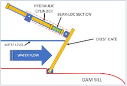
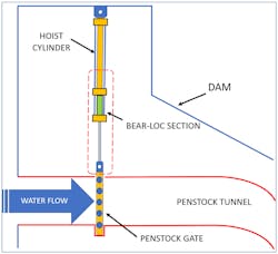
Areas with red dashed lines contain components the system depends on to lock a load in place or prevent drift when locked. In these illustrations, the lock takes the hydraulic circuit and power out of the equation for load safety and lockout. It also would hold the load even if the hydraulic fluid completely bled out and any or all the seals on the cylinder were damaged or lost. Only the cylinder body, rod and lock are needed to maintain the lock. Removing power engages the locking system; restoring power unlocks it and renews operation.
David Bickford is a principal engineer with York Precision Machining & Hydraulics.
