Size the cylinder right for proper servo operation
No matter how much attention is given to motion controller selection and programming, hydraulic system performance may be limited by incorrect sizing or physical location of components. A common design oversight is the use of undersized cylinders. Designers sometimes intend to increase piston rod speed by specifying a cylinder with a smaller bore — based on the assumption that for a given amount of oil flow, a smaller cylinder will produce quicker accelerations and higher velocities.
However, this only works for very light loads. For actuators moving moderate to heavy masses, acceleration, velocity, and deceleration are limited by the available force — not by oil flow. Because cylinder bore determines the force it can produce, if the bore is too small, the cylinder may be incapable of attaining the desired speeds or cycle times required by the application.
A real-world example
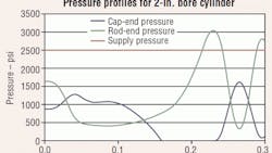
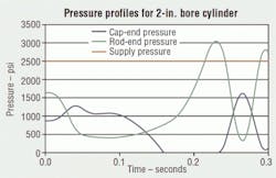
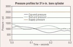
We were recently asked to diagnose problems with a system operating incorrectly. After obtaining specific application data, we performed a hydraulic system simulation. Our mathematical model suggested-that more force was necessary. The simulation was changed to evaluate cylinders with larger bores. The dramatic results, graphed in Figures 1 and 2, suggested replacing the existing 2-in. bore cylinders with 3¼-in. bore cylinders and replacing the hydraulic valves with appropriately larger ones.
Figure 1 shows how an undersized cylinder may not provide enough force to quickly decelerate a large load when extending. The cylinder cavitates (pressure goes to zero) on the cap end, and pressure on the rod end exceeds system pressure. The system is out of control because oil on the rod side is going back into the oil supply, thereby actually decreasing deceleration!
When the cylinder diameter is increased to 3¼-in., Figure 2, the piston rod accelerates the load at the same rate, but the pressure doesn't change as much because of the greater piston surface area. The cylinder pressures throughout the cycle are in the middle of the pressure range, with plenty of pressure drop across the piston to maintain positive control.
Increasing the cylinder bore increases the natural frequency (stiffness)of the system, allowing the motion controller to manage faster accelerations and decelerations, and yielding higher system performance when properly tuned. However, larger cylinders require larger valves and higher flow. Very large cylinders increase cost. And because large valves tend to be slower, at some point increasing valve size will no longer increase system response.
Force makes the system go
Force is directly related to cylinder size. Often, novice designers apply the familiar, but oversimplified, formula:
v = Q ÷ A,
where v is the piston velocity,
Q is the flow, and
A is the piston area.
But this equation is accurate only if the mass is zero. It should only be used to calculate flow: Q = v x A. The following "rule of thumb" formula takes into account the force needed to produce acceleration and the pressure drop required by servovalves for control. (Typically, servovalves are rated at 70 bar, approximately equal to 1000 psi.)
A = LP ÷ (PS — 1000 psi),
where LP is load pressure, and
PS is the system pressure.
This formula assumes that peak load occurs at peak speed. The peak load includes the force necessary to accelerate or decelerate the load, friction, and the load's weight if the system is vertical. Minimum system pressure should be used. This formula, which should be applied for both extend and retract directions, neglects the opposing force required to push oil out the opposite end of the cylinder. Therefore, the estimated size should be considered a minimum.
For high-performance motion, a second check should be made to ensure that the natural frequency of the system is higher than the frequency of motion generated by the motion profile. For example, if the frequency of acceleration is 5 Hz; the actuator's natural frequency should be three to four times higher:
Aavg = (f × 4)2× π × LS × WL ÷ (g × ß)
where Aavg is the average area of the piston,
f is the cycle frequency,
LS is the stroke length,
WL is the weight of the load,
g is the acceleration due to gravity (32 ft/sec2), and
is the bulk modulus (incompressibility constant) of oil (~200,000 psi).
This formula also tends to underestimate the correct cylinder bore because it makes some optimistic assumptions. The most significant is that the valve is mounted right on the cylinder. If this isn't the case, the cylinder stroke should be increased by about the length of the hose connecting the valve to the cylinder.
The area of the hose is smaller than that of the cylinder, but hose is more compliant than cylinder tubing. Hose or extra pipe between the valve and the cylinder complicate these calculations and reduce performance.
For the most critical applications, the VCCM equation, developed by Jack Johnson, takes into account additional variables and produces an excellent estimation of performance.
Peter Nachtwey is president of Delta Computer Systems Inc., Battle Ground, Wash. For additional technical information, e-mail him at [email protected] or visit www.deltamotion.com.
About the Author
Peter Nachtwey
President,
Peter Nachtwey has more than 35 years of experience developing industrial control systems for hydraulic, electric, and pneumatic applications. He graduated from Oregon State University in 1975 with a BSEE and served as an officer in the U.S. Navy until 1980. He became president of Delta Computer Systems Inc. in 1992. In addition to leading Delta’s engineering and R&D programs, he contributes widely to the mathematical understanding of control theory, especially in fluid power systems. He has also presented technical papers for IFPE, NFPA, FPDA, and various global technical conferences.


