Working Under Pressure: Using a Motion Controller for Pressure Control
By Peter Nachtwey, Delta Computer Systems Inc.
Controlling pressure is common in presses, grinding, and testing applications. These applications require the added value of pressure control which is much more sophisticated than what can be provided by the usual pressure relief valve or pressure regulator. Modern applications can take advantage of net force. This advantage can be obtained by using differential force control, where the pressure on either side of the piston is multiplied by the area and then these forces are subtracted from each other to get a net force.
Closed-loop control methods are now commonly used to control the pressure more accurately by compensating for viscosity changes. And field proven PID algorithms are much more sophisticated than the limited proportional control that mechanical devices with springs provide. This extra capability allows for controlling pressure while ramping and reducing overshoot.
What is pressure and why is it so valuable for precise control? Pressure is the force on a unit of area or total force divided by the area on which the force is applied. The pressure in a hydraulic system is caused by a force compressing oil in a confined volume or by adding fluid to the confined volume. For the purposes of this paper we will ignore thermal expansion.
The basic equation for pressure change is:
where ΔP is the change in pressure, is the fluid’s bulk modulus, and V is the volume of fluid
This equation tells us that change in the pressure is dependent on the change in the volume and the bulk modulus, which indicates how compressible a fluid is. For instance, oil has a bulk modulus of about 200,000 psi, and water has a bulk modulus of about 312,000 psi. What this means is that if the volume is compressed by 0.1% the oil’s pressure will increase by 200 psi and the water’s pressure will go up 312 psi. This illustrates that it is more difficult to compress water than to compress oil.
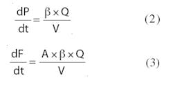
Consider that the following equations that define pressure and force as a function of time:
We can calculate the rate of change of pressure or force at any instant if we know the velocity, flow, and current volume — if we assume area and bulk modulus to be constant. We will focus on these two primary equations, 2 and 3, for this discussion.
Applying the equations
Pressure can be controlled in many ways, and one common method uses a servovalve or a proportional valve with a servo-cut spool. Equation 2 shows that to increase the pressure a little, fluid must be added to the volume. The fluid is added at a rate proportional to the rate of desired pressure increase. When the desired pressure is reached, the flow is stopped, and the system should maintain pressure indefinitely. In reality, a little leakage always exists, so the controller must add a little fluid at the rate of leakage. Therefore, the net flow, Q, remains zero and the rate of pressure change remains zero.
To decrease the pressure, the valve spool must shift so the fluid can exit through the valve. When the desired pressure is reached, the valve is again closed to maintain pressure. The main point here is that the rate of change in pressure is determined by the flow, not the pressure itself.
A typical proportional valve can be used to control pressure if the system is well designed. The key is to design the system with an intentional leak or orifice between the A and B ports of the valve. Equations 2 and 3 can be used to calculate the desired leakage rate if we know the maximum desired rate of decrease in the pressure or force.
The motion controller must command the valve to always supply fluid at the same rate as fluid loss through the bypass orifice just to maintain pressure. If the flow is too low, the pressure will drop as fluid escapes through the orifice. If the flow is too high, pressure will increase. The advantage of this method is that the system will be damped and not tend to oscillate while moving.
Control implications
In a hydraulic system, pressure can increase very quickly — say, in 1 msec. However, mechanical devices don’t respond that fast. Mechanical devices act on the pressure, not the rate at which pressure changes. Thus, it is easy for these devices to over shoot set points because there is no control of the pressure rate.
Consider the action of driving a car; you start to slow down when approaching a stoplight to make a smooth stop without overshooting into the intersection. Pressure control devices should do the same thing.
Important considerations
At least four criteria should be considered when controlling pressure:
1. Pressure sensor response time must be fast enough. Situations where the oil pressure increases by 200 psi in 1 msec are not uncommon when the material being compressed is not very compliant. A pressure sensor with a time constant in the msec range will not respond fast enough to the pressure change to be of any use. The pressure response time constant must be in the 100-μsec range to work. A rule of thumb is to always use sensors that take measurements at least ten times faster than the expected rate of change in what they measure.
2. The pressure sensor’s sample time must be quick and at fixed intervals. In applications such as metal presses, the pressure can change by hundreds of psi within a 10 msec scan.
3. The sample time must be constant. If a scan that is to be done nominally every 10 msec is actually done after 9 msec one time and 11 the next, the resulting pressure rate calculation will be off by at least 20%. Thus, a constant sample time is essential for accurately calculating pressure rate.
4. PLCs may not be the best option. The PID function in PLCs is designed for controlling temperatures or, perhaps, pressures of gases, but not for barely compressible fluid. PLC PIDs specify time constants in minutes when they should be in the millisecond range. A special PID controller designed for pressure control is required.
Control options
The first thing to understand is that position or pressure (force) can be controlled, but not position and pressure (force) at the same time. A cylinder can apply a force at any position only if an obstruction opposes it with the same force. A cylinder can perform a sinusoidal motion test and monitor the pressure at the same time but it cannot control the pressure at that same time it is controlling position because the pressure is determined by how much force the test piece exerts on the actuator. A cylinder can also perform a sinusoidal force or pressure test, but the position will be determined by how linear the “spring constant” of the test material is.
There may be no obstructions in the middle of the travel stroke, so to attempt controlling a pressure there makes no sense. The advantage of controlling just the pressure is that position is not taken into account.
You can easily change the set point to push or pull. However, you must be wary of no-load conditions. In these cases, the cylinder’s piston will accelerate until the force across it matches the force set point. When testing in pressure- or forceonly control, you should monitor the actuator speed for sudden drops in the load. This allows detecting that the load has gone and perhaps the actuator should switch to a position or velocity mode.
Position and pressure limits
Another option is using a position/velocity limit with a pressure or force limit. This works by running two control loops at the same time and sending only the minimum of the two control outputs to the valve. The result is a system that will go to either the position set point or the pressure set point, which ever is reached first. So if the cylinder was at the pressure set point, and the load suddenly disappeared, the pressure would drop and cause the pressure PID to generate a large control signal.
However, as the system speeds up, the velocity error decreases, and the control signal from its PID drops as the error drops. The lesser of the two signals will be from the velocity PID. So the cylinder will now be controlled by the position loop option, and the velocity set point will not be exceeded.
Setup and tuning of pressure or force control
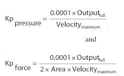
Tuning is the process of selecting the gains used to best control the position, velocity, pressure, or force in a motion control system. Tuning a pressure or force control system is different from tuning a position system because the cylinder does not move much while pressure tuning. The simplest way to tune the pressure or force is to dead head the system with all the gains set to zero. Then enter the set point and a small proportional gain only in the PID. The “small” proportional gains can be estimated by:
These equations give the person doing the tuning a place to start, which is often unknown when pressure tuning. You can start by finding out where the full output is 10 V or 40 mA or at 100% control signal to the valve, and the maximum velocity is then calculated using the VCCM equation from Basic Electronics for Hydraulic Motion Control by Jack L. Johnson P.E. It could also be determined by looking at a graph. The force equation must be divided by two times the area. This is due to the pressure increasing on one side of the piston and decreasing on the other. Keep in mind that the estimated proportional gain values will not be exact, but they will be in close enough for a good start.
When the proportional gain is enabled, the system pressure or force will go to the set point or close to it. Any error is usually due to leakage. The next step is to fix this by slowly increasing the integrator gain so the controller will compensate and add flow even when the error is zero.
Now that the system is controllable, it can be tuned for dynamic response. This is done by ramping the pressure between two pressures in the operational band. The pressure or force ramps should be slow at first because it is easier to maintain control. The PID gains should be adjusted so there is good control before moving to faster ramps and repeating the process.
Trying to tune the pressure or force PID to respond to a step change in the system is difficult and not desirable because pressure shocks are what cause leaks. Smooth pressure transitions are the way to go. When tuning pressure or force, the system will appear to be breathing as the pressure increases and decreases between the two set points.
Transitioning from position to force control
Many applications require the combination of pressure or force control with position control. Setting up such a system requires some knowledge of mechanics and the operational requirements. The transition from position to pressure-force control is relatively easy if the material being squeezed has lots of give to it, because it can absorb a lot of energy.
Conversely, metal-to-metal contact such as between a press and stop blocks makes the position to pressure or force transition more difficult because stop blocks don’t absorb much energy. You can adjust the speed at contact so the amount of kinetic energy of the actuator and any die or tool it is carrying matches the energy required to form or deform the work piece.
Simply put, if the actuator and tool move too quickly, pressure spikes will exist because the hydraulic system can’t react fast enough or dissipate that much energy. If the actuator approaches the work piece too slowly, the press will stall when the work piece is reached. Then the actuator must build up enough force to start forming the part. This is usually too slow and not desired.
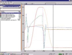
Tuning an axis that controls both position and force requires some special considerations. It helps to rely on plotting and tuning tools that are supplied by the motion controller manufacturer. For example, after you pick some initial and conservative PID and feed forward gains for the pressure closed loop, Delta’s RMCTools software uses command buttons in its Tuning Tools setup dialog boxes to command an axis to ramp to a specific pressure value in a specific period of time. This is done in both directions and looks at visual plot information, comparing target to actual values over time in order to determine if gain parameters for the pressure loop need to be changed.
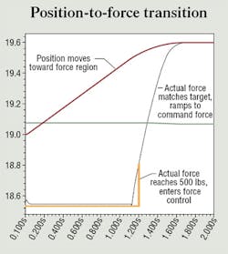
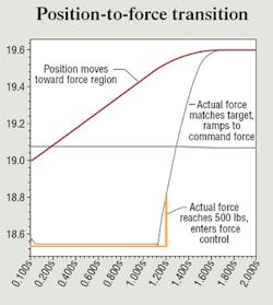
Figure 2 is a representative plot showing the operation of a metals press as the sequence transitions from position to force control. At the 0.1 sec point, pressure ramps to a desired force target and holds the actual force at the target force level for a short time during stamping of the metal part. Then, at approximately 0.4 sec into the cycle, the controller releases the actual force by switching out of force control and reverses the cylinder to complete the stamping cycle.
The next steps in the process include adjusting and re-adjusting P, I, D and, eventually, the force rate feed forward gains using the plots to optimize the tuning process. Once the pressure tuning is established, the next step is to tune the transition between position control and force control. This may require slowing the system down when transitioning from position closed-loop control to pressure closed-loop control.
Conclusion
Many applications involve pressure or force control, and electronic motion controllers can make the systems function smoothly and effectively if some key system design guidelines are taken into consideration.
For more information, contact the author at [email protected] or visit www.deltamotion.com.
About the Author
Peter Nachtwey
President,
Peter Nachtwey has more than 35 years of experience developing industrial control systems for hydraulic, electric, and pneumatic applications. He graduated from Oregon State University in 1975 with a BSEE and served as an officer in the U.S. Navy until 1980. He became president of Delta Computer Systems Inc. in 1992. In addition to leading Delta’s engineering and R&D programs, he contributes widely to the mathematical understanding of control theory, especially in fluid power systems. He has also presented technical papers for IFPE, NFPA, FPDA, and various global technical conferences.
