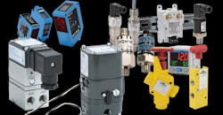
Pneumatics technology is a popular option for machinery and industrial devices because it is clean, fast, and economical. The most common form of accomplishing pneumatically driven motion is by applying or removing air pressure to extend or retract a cylinder, but there are also rotary actuators and even air motors. All of these devices can be automated using digital controllers integrated to command the pneumatics and make the equipment move as desired.
This motion is often simply a discrete on-or-off mode, as opposed to a continuously variable analog mode, but that’s not always the case. Linear actuators can be configured for multiple intermediate stops, or with modulating options for variable positioning. For process control valves, pneumatic valve positioners can perform this function, and they often need to be monitored to ensure accurate activation.
Many users find that they can take full advantage of the benefits offered by pneumatic fluid power delivery by integrating more advanced analog control features. This article examines how users can identify opportunities and select the right components to incorporate analog controls into their pneumatic systems.
Discrete vs. Analog Signals
For equipment requiring more control complexity than basic selector switches and indicator lights, automation is usually performed with smart relays, programmable logic controllers (PLCs), or programmable automation controllers (PACs). These computing devices connect to the outside world through input/output (I/O) points.
Basic automation needs are most often handled with discrete signals that are on or off. This can be a discrete output (DO), such as to command a solenoid valve, or a discrete input (DI), for monitoring a limit or pressure switch. Discrete signals are easy to select, configure, and install, with the proper voltage being the main concern.
Analog input signals, on the other hand, are somewhat more complex. Devices such as analyzers and transmitters produce a range of signals. Typical analog input signals could be temperature, level, weight, and speed. However, for pneumatic systems, common analog inputs are typically pressure, position and flow. Analog output signals can be used to command a valve position or a pressure controller.
Incorporating analog signals requires a little more planning as compared to discrete signals.
Analog Signal Methods
When incorporating analog signals into a control system, it is crucial to coordinate the signal method with the control system, as well as to ensure that the scaling represents the measured variable properly.
Standard hardwired analog signals are usually transmitted as a variable current or voltage. Typical ranges are 4 to 20 mA, 0 to 10 V dc, or –10 to +10 V dc. For many industries, the 4- to 20-mA signal is the most popular, and it offers the additional benefit of positively identifying a failed instrument or wire connection if the signal ever goes below 4 mA.
Another option is to use a digital communication protocol if it is available on the pneumatic device and the controller. Some high-end instruments may offer an Ethernet-based protocol, like EtherNet/IP. If individual sensing devices are being used, they are more likely to offer a local communications option like IO-Link. This protocol enables the sensor to perform a traditional hardwired function, but also transmits an additional digital signal. With the appropriate hub, this digital signal can be processed and made available over a higher-level protocol like EtherNet/IP.
Regardless of how the analog signal is transmitted, it must be supported and interpreted correctly by the control systems. The user must identify the normal sensing range, the possible under-range or over-range conditions, and the engineering units involved. For instance, if a designer needs to monitor a pressure that ranges from 0 to 80 psi, they may choose a standard pressure transmitter indicating 0 to 100 psi using 4-20 mA. In this case, 4 mA corresponds to 0 psi while 20 mA corresponds to 100 psi. Perhaps a signal of less than 3.8 mA or more than 20.2 mA indicates a wiring or transmitter problem. These same scaling considerations are equally applicable to analog output signals.
Next, we’ll look at control system and field device specifications to check when working with analog signals.
Specification Details
Beyond the basic signal method and scaling are some more involved details. PLCs themselves are fast and accurate, but when implementing analog signals the system must be considered as a whole. In addition to those described above, some other details impacting analog signals are:
- Resolution
- Accuracy
- Stability
- Electrical isolation
Most PLC analog points offer at least 12-bit resolution, meaning the signal is processed into 4,096 counts. This is adequate for most applications, but specific cases may require higher resolution, typically up to 16-bit, which offers 65,536 counts.
Accuracy and stability are a function of the transmitter specifications and how well the transmitter can produce a signal representing the actual field condition. Best accuracy is obtained when sizing an instrument to match the application. For instance, in the previous example where a user is interested in pressures ranging up to 80 psi, it is appropriate to select a transmitter able to measure up to 100 psi. If the user selected a transmitter able to measure up to 800 psi, they would only be using the bottom 10% of the available range and could expect a less accurate signal.
Electrical isolation is partly a function of the transmitter and the PLC analog points but mostly involves the field installation. Analog signal cables are low voltage and are susceptible to electrical noise, so they should be routed away from higher voltages. Whenever possible, the analog signal cables should be the shielded type with the shield grounded at one end. Even better is to install analog cables in metal conduit whenever possible, with no higher-voltage wiring in the conduit.
One additional note is that some instruments are multi-function, able to provide discrete, analog, and even digital communications. Once all the signal and specification details addressed, it is time to look at where analog signals can be used in pneumatic systems.
Pneumatic Applications
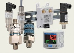
Pneumatic pressure sensors are plumbed into the header or line being monitored, and these sensors then transmit an associated AI signal (Fig. 1). Some styles are installed in a control panel and require a tubing run to the process connection. There are many types of sensors that are configured for field installation and can be plumbed directly into pipe fittings. Some pressure transmitters have an on-board indicator, or users may need to install a means of local indication.
1. These AutomationDirect ProSense sensors monitor pressure in many process applications, providing discrete and analog output signals in wide measurement ranges for use in both pneumatic and hydraulic circuits.
The simplest way a control system can use a pressure transmitter signal is to ensure that a pneumatic line has the proper pressure to operate the equipment. More advanced applications may be used to command and monitor the air pressure applied to actuators for a mechanism, such as to provide a variable clamping force for handling different products.
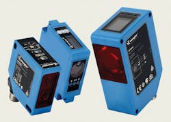
Determining the analog position directly on-board a pneumatic linear actuator is possible but not as common an application, but using position sensors on the driven equipment is a good option to determine the exact location of the mechanism. One very accurate measuring technology uses a laser to determine distances ranging from millimeters up to meters (Fig. 2). The control system can use this signal to extend or retract a cylinder as needed to achieve the target position. Once the equipment has moved to the desired location, air can either be removed from or applied to both sides of the cylinder as needed to hold position.
2. Laser distance sensors are a highly accurate way to sense equipment positions so control systems can command pneumatics as needed.
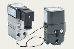
Varying pneumatic pressures can be commanded with a current-to-pneumatic (I/P) transducer (Fig 3). The current signal is typically 4-20 mA, and I/P transducers are available with outputs ranging from a few psi up to more than 100 psi. Analog pneumatics of this type can be used to operate a damper control valve, and pneumatics are a good choice for use in any hazardous area location as an alternate to intrinsically safe electrical controls.
3. Current-to-pressure (I/P) transducers convert analog control system signals into varying pneumatic pressures.
Analog controls can be a very effective addition to pneumatically actuated equipment, but there are some best practices to consider. Any critical driven equipment that relies on analog position feedback should also have end-of-travel discrete limit switches and mechanical stops incorporated to prevent overtravel in the event of a sensor failure. Similarly, any critical pressures being monitored or controlled should incorporate high- or low-pressure switches as an additional precaution.
Analog Controls Provide More Options
Incorporating analog instruments and controls into pneumatically-operated applications adds an entire new range of functionality options. Following the guidelines in this article will help designers select the right signal range, field device, and control elements to achieve reliable analog control.
Valves Help Ensure Safe Maintenance
Safety isn’t just a good thing to do; it’s the law. OSHA Standard 3120, commonly referred to as lockout-tagout, establishes minimum requirements for controlling hazardous energy, such as electricity and compressed air. Employers must establish an energy-control program to ensure that employees isolate machines from energy sources and render them inoperative before any employee services or maintains them.
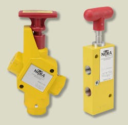
Shown here are two examples of pneumatic lockout-tagout valves. At left is the SLV-12N34N, which has 1/2-in. female inlet and outlet ports and ¾ -in. female exhaust port. The SLV-14N38N has 1/4-in. female inlet and outlet ports and 3/8-in. female exhaust port.
An employer’s energy-control program must:
- Establish energy-control procedures for removing the energy supply from machines and for putting appropriate lockout or tagout devices on the energy-isolating devices to prevent unexpected reenergization. When appropriate, the procedure also must address stored or potentially reaccumulated energy.
- Train employees on the energy-control program, including the safe application, use, and removal of energy controls.
- Inspect these procedures periodically (at least annually) to ensure that they are being followed and that they remain effective in preventing employee exposure to hazardous energy.
Winn Paulk is Automation Controls Group product manager at AutomationDirect, Cumming, Ga. For more information, visit www.automationdirect.com or call (800) 633-0405.
About the Author
Winn Paulk
Automation Controls Group Product Manager
Winn Paulk is the Automation Controls Group product manager at AutomationDirect. He has been involved in the design, programming, installation, and maintenance and repair of a wide variety of automated equipment for over 25 years in multiple industries. He joined AutomationDirect 10 years ago as a technical support engineer and has been a product engineer in Automation Controls Group for seven years. Prior industries he has worked in include industrial fabrics, die cast and machining, assembly, and building products.

Leaders relevant to this article:
