Zoned Approach Simplifies Functional Safety of Designs
Manufacturers must prevent workplace accidents by guarding against safety risks. Reaching the desired safety level can be challenging, as it can add complexity and reduce productivity. This article reveals how a unique approach, known as Zoned Safety, reduces complexity in the design of redundant pneumatic safety circuits and improves machine productivity. It explains the advantages of the concept over the traditional method of pneumatic safety circuit design using dump valves, listing the benefits for both equipment manufacturers (OEMs) and end-users.
A recent study by the Occupational Safety and Health Administration (OSHA) found that manufacturing accounted for 26% of work-related hospitalizations and 57% of work-related amputations—both higher than any other industry in the United States. Statistics such as these explain why, for both OEMs and end-users, there is considerable interest and focus today on improving production machinery safety. It is vital for manufacturing companies to ensure the safety and health of their employees who are engaged in the installation, operation, adjustment, and maintenance of production equipment.
However, production machinery is becoming more complex, and the high number of interactions that take place between operators and machines makes it challenging for a company to safeguard its people and assets.
A strong emphasis on safety is especially important for those industries using machines that incorporate horizontal or vertical movement and require intermittent to frequent operator interaction (e.g., load/unload operations). These industries include automotive, packaging, pharmaceutical, process, stamping, general machining, assembly operations, and tire production. However, guarding against safety risks isn’t easy; when changes are made to improve a machine’s safety, operations can become even more complex or more restrictive.
These safety measures often incorporate time-consuming procedures to stop machine operation, isolate energy, resolve issues, and restart processes—all of which translate into lost production time. Even so, safety must always remain the number one priority, as a safety incident can result in damage to equipment, unforeseen costs, loss of productivity from shutdowns, and—more seriously—injury to workers, or even loss of life of life in a worst-case scenario.
By implementing the right procedures and technologies, OEMs and end-users can create safer manufacturing environments that reduce risk to operators without compromising productivity. While end-users are responsible for training employees in safe work practices, OEMs must design and build machines that are safe and compliant with government and industry regulations and directives. To accomplish this task, OEMs must conduct a risk assessment to identify the health and safety risks that exist. Machines must then be designed and constructed using methods that will reduce these risks.
Machinery Directive and Safety Standards
Over the past two decades, standards have evolved to guide OEMs in producing safe equipment. In Europe, Machinery Directive 2006/42/EC became law in 2009, with the aim of protecting people’s health and safety during installation, use, adjustments, and maintenance of machinery. This directive is intended for manufacturers, importers, and dealers of machinery and safety components, and applies to new machines built or used in Europe. It harmonizes the level of safety of products designed and produced by different manufacturers.
The directive is supported by various standards. For example, ISO 13849-1 covers the design and construction of safety-related parts of control systems for machinery. These include basic concepts, principles for design, and engineering aspects that can be applied to production equipment to satisfy machinery safety.
ISO 13849-1 introduces three key concepts for the design of machinery and their safety functions. These are:
- The use of a risk analysis prior to design
- Consideration of the quantitative aspects of the safety functions, as well as a qualitative approach
- The use of performance levels (PL) to assess the ability of safety-related parts of control systems to perform a safety function under foreseeable conditions (they are defined in terms of probability of dangerous failure per hour)
According to the European Statistics on Accidents at Work (ESAW), the period between 2009—when Machinery Directive 2006/42/EC was applied—and 2013 saw non-fatal accident figures fall by 12% and the number of fatal accidents drop by 15%. The incidence rate of accidents (accidents per 1,000 employees) in manufacturing fell by 9%, and the amount of fatal accidents in manufacturing went down by 13% over the same period.
Even though this directive is initiated in and applies to Europe, it is important to have globally designed solutions that not only meet the European directive, but benefit manufacturers and users worldwide.
Shortcomings of Traditional Pneumatic Safety Circuit Design
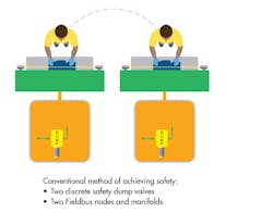
Visualize a production line with an operator loading a part inside a welding machine. When the operator enters or reaches into the machine environment, all equipment motion must stop to ensure safety. To meet the necessary safety requirements, the design of machinery that has pneumatic components has traditionally involved employing separate safety circuits with redundant dump valves, which shut off air supply, release air, and disable operation of the entire machine.
Although this approach has been used for many years, it has certain drawbacks. It wastes energy by repeatedly dumping all the compressed air in the entire machine, which must then be recharged upon start-up. Valuable time is taken up as operators are forced to wait for extended periods as entire systems restart. This method also adds significant complexity and unnecessary cost to machine design, manufacture, and installation because it requires more expensive components and more complicated control structures with a safety system required for each zone.
Without these control structures, the sudden reintroduction of air into a pneumatic system can cause unintended motion of components. This increases the risk of damage to the machinery itself, or else causes the products retained by jigs, fixtures, or clamps to move or drop—resulting in damage, spills, lost product, and scrap. By trying to avoid this damage and maintain expected output, some operators may be tempted to allow some machinery to remain active when it should not be, thereby inadvertently exposing themselves and their operations to increased risk.
It is worth noting that when used in a continuous cycle fashion (as identified in Fig. 1), a redundant dump valve’s lifecycle capability may not allow the user to achieve the required Performance Level (PL).
1. When used in a continuous cycle fashion, a redundant dump valve’s life cycle capability may not allow the user to achieve the required Performance Level.
A Better Way to Achieve Safe Machine Operation
There are three basic safety functions in pneumatic circuits: release of energy, return home, and stop/inhibit motion. Depending on a machine’s pneumatic content, any of these safety functions could be the most efficient and safest method. The traditional dump valve solution is the most appropriate for some applications. However, in many instances, it would be more efficient to stop/inhibit motion, return home, or use some combination of the safety functions tailored to the specific safety requirements of the equipment.
It is sometimes also more efficient to inhibit specific portions of a machine while the rest of the machine operates normally. This option has led to the emergence of a concept called Zoned Safety, an innovative technology that provides a simpler and less expensive approach to safety that meets the requirements of Machinery Directive 2006/42/EC and the ISO 13849-1 standard.
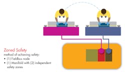
Zoned Safety technology—introduced by Emerson on its ASCO Numatics manifold—simplifies the design of a redundant pneumatic safety circuit. It gives an engineer the capability to define and set up as many as three independent electro-pneumatic safety zones, while also allowing independent non-safe sections to co-exist within a single valve island assembly (Fig. 2). The ASCO Numatics Zoned Safety manifold has been evaluated by TÜV Rheinland and is compatible up to category 3 PLd. Available with various fieldbus protocols, this is a suitable option for most manual load/unload stations and a wide variety of other industrial applications. Alternative solutions enable the isolation of only one zone per manifold, which can make them more expensive and complex.
The zoned safety concept allows for customized designs that are both safe and efficient. Because the safety zones can be configured to shut down compressed air and electrical power only to the group of valves that control the machine’s specific motion in the operator’s vicinity, the entire machine need not be shut down. This ensures operator safety while allowing the rest of the machine to keep producing, even though these safety circuits are enabled.
2. Safety zones can be configured to shut down compressed air and electrical power only to the group of valves that control the machine’s specific motion in the operator’s vicinity, eliminating the need to shut down the entire machine.
When zoned safety capability is designed into a manifold platform, no redesign or safety redundant dump valve is required for zone control, and users have optimal choices when selecting valve options, accessories, and flow requirements. The assembled product is very similar to a standard valve manifold that has been used by OEMs and machine builders for many years.
The Zoned Safety approach should not be confused with Lockout-Tagout (LOTO), which is a mode used when a machine is being serviced. In this mode, maintenance personnel engage the dump valve in the machine’s pneumatic system, removing and exhausting compressed air energy. Then the machine power is disconnected, and a physical lock is installed on the dump valve. This ensures that the machine’s pneumatic system cannot be inadvertently restarted.
Potential Benefits
There are several ways OEMs can benefit from the Zoned Safety valve manifold concept. Perhaps the most important is the ability to greatly simplify the design of a redundant pneumatic safety circuit with a manifold system. No longer is a separate safety circuit—with multiple redundant dump valves and other components that add complexity and higher cost—required to safely isolate sections of the machine.
The ability to easily and cost-effectively design multiple independent safety circuits into a single pneumatic manifold can reduce the number of safety system components by up to 35%, optimizes the use of safety networks, and requires less plumbing. The approach also shrinks the size of the safety system and enables valuable space within the machine and the manifold to be used for other purposes.
For most OEMs, designing multi-zoned safety circuits with a Zoned Safety manifold should be a familiar and user-friendly experience. Only the ability to redundantly remove power and pilot air to the safety system valves has been added. For equipment owners and operators, Zoned Safety can simplify and reduce cost while optimizing the safety of their machines. Best of all, productivity and asset availability can be improved since the user does not have to shut down the entire machine when safety circuits are enabled.
Applying Zoned Safety in an Automation Workflow
An automated machine can have three loading stations. As parts move down the line, an operator adds a stamped metal part to the welded assembly. To avoid injury, the operator should not put his hands into the active loading area. To ensure safety, the operator must walk through a light curtain that disables the power and pilot air (only to the redundant pneumatic valves controlling the moving components in the work station), preventing unwanted motion. He loads the part into a fixture, walks back out through the light curtain, and initiates operation, thus restarting the machine.
The operator’s safety must be guaranteed while in the loading zones per Machinery Directive 2006/42/EC and the ISO 13849-1 standard. The conventional way to implement a safety function would be to have one manifold dedicated to the safety circuit in the first loading station. Feeding that manifold would be an expensive redundant safety dump valve. A duplicate manifold and dump valve would be installed for the safety circuits in the second and third loading zones as well.
With a Zoned Safety approach, a much simpler design is possible that allows safety operation without the need to dump air to the entire manifold. Three independent zones within a single manifold with Zoned Safety capability would independently control the safety function in the three loading stations. The additional manifolds, dump valves, and fieldbus nodes of traditional methods would not be needed.
Conclusion
Zoned Safety design is an integrated approach to safety control where multiple independent safety zones can be created within a single pneumatic manifold system. Air and power are disabled only to the components controlling equipment in the operator’s vicinity. The rest of the machine can remain in operation when these safety circuits are enabled. Zoned Safety greatly simplifies safety circuit design and reduces the number of system required components. Designers should consider this technique for any pneumatically controlled production equipment requiring compliance with Machinery Directive 2006/42/EC and the ISO 13849-1 standard.
Jeff Welker is project manager for Fluid and Motion Control at Emerson. For more information on zoned safety and other pneumatic automation techniques, click here.
About the Author
Jeff Welker
Project Manager, Fluid and Motion Control

Leaders relevant to this article:


