Safe application of 3-position air valves
Confusion often exists regarding the application of 3-position valves with double acting pneumatic cylinders for emergency stop and jog-type cylinder applications. Many times, the designer is asked to provide these actions when they are not necessary and without realizing the additional complexity and cost required.
Each 3-position application should be examined closely for the following:
• Is there a requirement to stop the cylinder mid-stroke?
• Is jogging of the cylinder, extend or retract, required?
• Is emergency stop of the cylinder, during extend or retract, absolutely necessary?
Improper application of 3-position air valves to satisfy these may, during start-up or repair, create additional safety hazards. This discussion will point out those hazards.
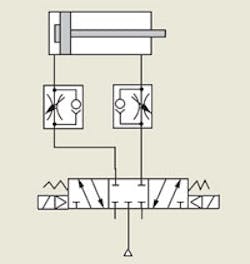
All ports blocked
Valves with all ports blocked in the center position Figure 1, are frequently used to stop or jog an air cylinder mid-stroke. When stopping or jogging mid-stroke is required, be aware that with the valve spool centered, air is trapped in the cylinder. Therefore, leakage from a fitting, piston or rod seal, or the valve itself can cause the cylinder to drift. Also, when exhausted through a lockout-and-exhaust valve, air may still be trapped in the cylinder — for example, a vertically mounted cylinder supporting a load. When the cylinder is opened, the load may drop unexpectedly.
Finally, if the lockout-and-exhaust valve is opened during startup, the blocked center condition does not allow air to return to the cylinder. When full pressure is applied to the valve, and the valve is actuated, the first stroke of the cylinder may be at high speed due to the lack of air in the cylinder. This uncontrolled startup can cause internal damage to the cylinder, the machine or both.
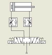
In the first two cases, the actions often occur when least expected. If you must provide jog or emergency stop, a valve with cylinder ports open to exhaust, Figure 2, could be used. The exhausted cylinder condition does not allow the cylinder to hold position against external loads. However, if the cylinder’s piston rod is pushed or pulled from its normal extended or retracted position, actuating the valve can cause an uncontrolled startup — resulting in rapid cylinder movement from a lack of pressurized air in the cylinder.
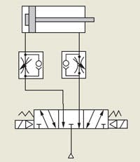
Inlet open to cylinder ports
Supplying both sides of the piston with equal pressure in a single-rod cylinder, Figure 3, creates an unequal output force, which causes the piston rod to extend. A regulator sometimes is installed in the air line that supplies the cap end of the cylinder to equalize the force. However, this would be an improper application of a regulator because the repeated pressure cycling could lead to premature failure of the regulator. Furthermore, this configuration cannot be used to support vertical loads.
Cylinder ports open to exhaust
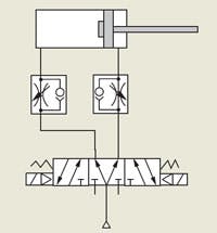
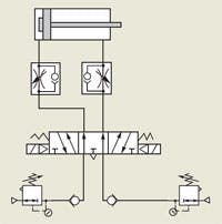
With dual pressure applied, this circuit, Figure 4, provides the system with make-up pressure to overcome fitting, valve, and rod seal leakage. Check valves provide backpressure to the cylinder to help hold against external loads. Each check valve also protects the regulators against sudden inertial loads.
An independent pressure regulator allows adjustment for piston area differential and vertical loads. When the lockout-and-exhaust valve is opened during startup, air flows to both ends of the cylinder to prevent over-running motion when the valve is first actuated.
Caution — When air is exhausted by a lockout-and-exhaust valve, air may still be trapped in the cylinder. A vertical cylinder supporting a load may unexpectedly drop when the cylinder line is opened or disconnected. Machines requiring this method of control should not be incorporated into manifold assemblies. They must be piped as individually mounted valves.
Cylinder ports open to exhaust
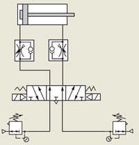
With dual pressure applied, this circuit provides system pressure to overcome fitting, valve, and rod seal leakage. The regulator can be adjusted to compensate for piston differential area for providing jog or emergency stop control.
When air is exhausted by a lockout-and-exhaust valve, all air is vented, so none is trapped. During start-up, when the lockout-and-exhaust valves are open, air is supplied to both ends of the cylinder to prevent an uncontrolled startup when the valve is first actuated.
Note, however, that this circuit is not recommended for vertical cylinders supporting heavy loads. Some drift of the cylinder may occur from relieving regulators when centering the valve.
Summary
Evaluation should be made to determine the need for a 3-position valve. Many times during emergencies or loss of electrical power, a spring-return, 2-position valve may be used if no pinch point exists or an action is guarded and the cylinder may return to its normal position.
Two-position, detented valves are normally used on clamps and other devices to maintain cylinder position during loss of electrical power. They may be energized during extension to return to the normal position during emergencies, provided guards are present and no pinch points exist.
Three-position valves should be held energized except during jog or emergency stop conditions. This maintains full pressure on one end of the cylinder to provide full force and prevent drifting.
Cylinders controlled by 3-position valves need leak-tight piston seals. Seal leakage allows pressurized air to bypass the piston, causing the cylinder to drift.
Regulators should not be installed between the valve and the cylinder. When in doubt, the circuit in Figure 4, with regulators and check valves, serves as a good default configuration.
Air cylinders should be depended on to hold a load in mid-position. When this is required, a method of positive location control must be used, such as a rod lock.
This material was provided by Norgren Inc. For more information, visit www.norgren.com.
Lightning strikesThe Fluid Power Designers’ Lightning Reference Handbook has been one of the most requested technical guides by just about anyone involved in any aspect of fluid-power design, installation, and maintenance. The latest edition, 8.1, contains nearly 200 pages that are packed with updated information, including descriptions of ANSI and ISO standards, conversion factors, dimensional and performance data for electric motors, formulas for calculating fluid power design parameters, specifications on fluid flow and components, a glossary, and a list of common abbreviations. And that’s not all. It also has detailed chapters on hydraulic fluids and fluid cleanliness, actuator calculations, and fluid conductors (hose, pipe, tubing, fittings, flanges, and couplings). Additional information is provided on reservoir design, heat transfer, accumulators, noise abatement, and pump parameters. To order a copy, visit the H&P Bookstore by clicking here. |
