Pressure control valves assist hydraulic systems in many ways—from keeping system pressures below a desired limit to maintaining a set pressure in circuits. The most widely used valves for controlling pressure include relief, reducing, sequence, and counterbalance valves.
Relief Valves
Most hydraulic systems are designed to operate within a preset pressure range. This range is a function of the forces the actuators in the system must generate to do the required work. Without controlling or limiting these forces, the hydraulic components (and expensive equipment) could be damaged. Relief valves prevent this hazard. They are the safeguards that limit maximum pressure in a system by diverting excess fluid when pressures become too high.
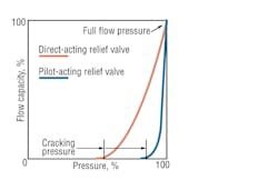
The pressure at which a relief valve first opens to allow fluid to flow through is known as cracking pressure. When the valve is bypassing its full rated flow, it is in a state of full-flow pressure. The difference between full-flow and cracking pressures is sometimes known as the pressure regulation characteristic, or pressure override.
Sometimes this pressure override is not objectionable. However, it can be a disadvantage if it wastes power (because of the fluid lost through the valve before reaching the maximum setting). This can further permit maximum system pressure to exceed the ratings of other components.
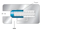
Relief valves come in two varieties: direct acting and pilot operated. Direct-acting valves consist of a poppet or ball (poppet will be used for simplicity of discussion), held exposed to system pressure on one side and opposed by a spring of preset force on the other. In a fixed, non-adjustable, normally closed relief valve (Fig. 1), the force exerted by the compression spring exceeds the force exerted by system pressure acting on the poppet. The spring holds the poppet tightly seated. A reservoir port on the spring side of the valve returns leakage fluid to tank.
1. Simple, direct-acting relief valve has no adjusting screw and, therefore, opens at a fixed, preset pressure as controlled by the force from a compression spring.
When system pressure exceeds the valve spring setting, the fluid unseats the poppet, allowing a controlled amount of fluid to bypass to the reservoir, maintaining system pressure at the valve setting. The spring re-seats the poppet when enough fluid is released for system pressure to drop below the valve spring setting.
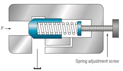
Because fixed relief valves are limited to the single setting of their spring, most relief valves are adjustable. This is commonly achieved with an adjusting screw acting on the spring (Fig. 2). By turning a screw in or out, the operator compresses or decompresses the spring respectively. The valve can be set to open at any pressure within a desired range. Aside from the adjustable feature, this valve works just like the fixed valve in Fig. 1.
2. Adjustable, direct-acting relief valve blocks flow through the valve until force of system pressure on a poppet overcomes the adjustable spring force and downstream pressure.
Spring-loaded poppet valves are generally used for low flows. They have low internal leakage below cracking pressure and respond rapidly, making them ideal for relieving shock pressures. They’re often used as safety valves to prevent damage to components from high pressure surges or to relieve pressure caused by thermal expansion in locked cylinders. The differential between cracking and full open pressure on spring-loaded poppet relief valves is high. For this reason, they are not recommended for precise pressure control.
Another type of direct-acting relief valve has a guided piston. In this valve, a sliding piston — instead of a poppet — connects the pressure and reservoir ports. System pressure acts on the piston and moves it against a spring force. As the piston moves, it uncovers a reservoir port in the valve body.
These valves have a fast response but may be prone to chatter. They can be damped, but this slows their reaction time. They are reliable and can operate with good repetitive accuracy if flow doesn’t vary widely. Valves with hardened-steel pistons and sleeves have a long service life. They may leak slightly below cracking pressure unless the pistons are sealed.
Guided-piston relief valves generally are used for pressures below 800 psi, although they can be made with heavier springs for higher pressures. The heavier springs give the valve a greater differential and, consequently, increase valve size.
Pilot operated relief valves (Fig. 3), are most-often used in applications involving large flow with a small pressure differential. The pilot-operated relief valve operates in two stages. A pilot stage, which consists of a small, spring-biased relief valve (generally built into the main relief valve), acts as a trigger to control the main relief valve. However, the pilot may also be located remotely and connect to the main valve with pipe or tubing.
3. Pilot-operated relief valve has an orifice through the poppet, which is held closed by the force from a spring and system pressure acting on larger poppet area at spring end.
The main relief valve is normally closed when the pressure of the inlet is below the setting of the main valve spring. Orifice B in the main valve (Fig. 3) permits system pressure fluid to act on a larger area on the spring side of the poppet, so the sum of this force and that of the main spring keep the poppet seated. At this time, the pilot valve is also closed. Pressure in passage B is the same as system pressure and is less than the setting of the pilot valve spring.
As system pressure rises, the pressure in passage B rises as well, and, when it reaches the setting of the pilot valve, the pilot valve opens. Fluid is released behind the main valve through passage B to the drain port. The resulting pressure drop across orifice A in the main relief valve opens it, and excess fluid flows to tank, preventing any further rise in inlet pressure. The valves close again when inlet oil pressure drops below the valve setting.
Pilot-operated relief valves typically have relatively low internal leakage until pressure reaches 80 to 90% of the pressure setting, at which point the pilot stage may begin to open. These valves are best suited for high-pressure, high-volume systems. Although their operation is slower than that of direct-acting relief valves, pilot-operated relief valves maintain more stable pressure while relieving. Figure 4 plots the operating characteristics of direct-acting and pilot-operated relief valves.
4. Comparison of action of relief valves at cracking and full-flow pressure.
Pressure-Reducing Valves
The most practical components for maintaining secondary, lower pressure in a hydraulic system are pressure-reducing valves. Pressure-reducing valves are normally open 2-way valves that close when subjected to sufficient downstream pressure. (Three-way valves are also available.) They come in two types: direct-acting and pilot-operated.
Direct acting—A pressure-reducing valve limits the maximum pressure available in a secondary circuit regardless of pressure changes in the main circuit, and as long as the work load generates no back flow into the reducing valve port. When back flow does occur, the valve will close (Fig. 5).
5. Direct-acting, pressure-reducing valve is held open by spring force. Increasing pressure at outlet port moves the spool to the right, closing the valve.
The pressure-sensing signal comes from the downstream side (secondary circuit). This valve operates in reverse fashion from a relief valve (which senses pressure from the inlet and is normally closed).
As pressure rises in the secondary circuit (Fig. 5), hydraulic force acts on area A of the valve, closing it partly. Spring force opposes the hydraulic force, so that only enough oil flows past the valve to supply the secondary circuit at the desired pressure. The spring setting is adjustable.
When outlet pressure reaches that of the valve setting, the valve closes except for a small quantity of fluid that bleeds from the low-pressure side of the valve, usually through an orifice in the spool, through the spring chamber, to reservoir.
Should the valve close fully, leakage past the spool could cause pressure buildup in the secondary circuit. To avoid this, a bleed passage to tank keeps it slightly open, preventing a rise in downstream pressure above the valve setting. The drain passage returns leakage flow to tank. (Valves with built-in relieving capability are also available to eliminate the need for this orifice.)
Constant- and fixed-pressure reducing valves supply a preset pressure, regardless of main circuit pressure, as long as pressure in the main circuit is higher than that in the secondary. Constant-pressure-reducing valves balance secondary circuit pressure against the force exerted by an adjustable spring, which tends to open the valve. When pressure in the secondary circuit drops, spring force opens the valve enough to increase pressure and keep a constant reduced pressure in the secondary circuit.
Fixed-pressure-reducing valves supply a fixed amount of pressure reduction regardless of the pressure in the main circuit. For instance, assume a valve is set to reduce pressure by 250 psi. If main system pressure is 2,750 psi, reduced pressure will be 2,500 psi.
The valve operates by balancing the force exerted by the pressure in the main circuit against the sum of the forces exerted by secondary circuit pressure and the spring. Because the pressurized areas on both sides of the poppet are equal, the fixed reduction is that exerted by the spring.
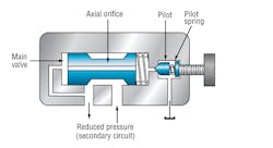
Pilot-operated—The spool in a pilot-operated pressure-reducing valve is balanced hydraulically by downstream pressure at both ends (Fig. 6). A light spring holds the valve open. A small pilot relief valve, usually built into the main valve body, relieves fluid to tank when reduced pressure reaches the pilot valve’s spring setting. This fluid flow causes a pressure drop across the spool. Pressure differential then shifts the spool toward its closed position against the light spring force.
6. Pilot-operated, pressure-reducing valve has reduced pressure on both ends of the spool. A light spring holds the spool open.
The pilot valve relieves only enough fluid to position the main valve spool or poppet so that flow through the main valve equals the flow requirements of the reduced-pressure circuit. If no flow is required in the low-pressure circuit during a portion of the cycle, the main valve closes. Leakage of high-pressure fluid into the reduced-pressure section of the valve then returns to the reservoir though the pilot-operated relief valve.
Pilot-operated pressure-reducing valves generally have a wider range of spring adjustment than direct-acting valves, and they usually provide greater repeatability. However, fluid contamination can block flow to the pilot valve, keeping the main valve from closing properly. Pilot-operated valves with built-in reduced pressure system relieving capability also are available.
Sequence Valves
In circuits with more than one actuator, it’s often necessary to drive the actuators, such as cylinders, in a definite order or sequence. This can be done with limit switches, timers, or other electrical control devices.
Sometimes this can be achieved by sizing cylinders according to the load they must displace. The cylinder requiring the least pressure to move its load extends first. At the end of its stroke, system pressure increases and extends the second cylinder. This continues until all cylinders are actuated.
However, in many installations, space limitations and force requirements determine the cylinder size needed for the job. In this case, sequence valves can be used to actuate the cylinders in the required order.
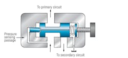
Sequence valves are normally closed 2-way valves that regulate the sequence in which various functions in a circuit occur (Fig. 7). They resemble direct-acting relief valves except that their spring chambers are generally drained externally to tank, instead of internally to an outlet port.
7. Sequence valve is a 2-way valve held closed by an adjustable spring and opened by pressure at the inlet port acting on the left of the spool.
Normally, a sequence valve routes pressurized fluid to a second function only after an earlier function has been completed. When normally closed, a sequence valve allows fluid to flow freely to the primary circuit to perform its first function until the valve’s pressure setting is reached.
When the priority function is satisfied, pressure in the primary circuit rises and is sensed in pressure-sensing passage A. This pressurizes fluid acting on the spool and overcomes the force exerted by the spring. The spring is compressed, the spool shifts, and fluid flows to the secondary circuit.
Sequence valves sometimes have check valves that allow unrestricted reverse flow from the secondary to the primary circuit. However, sequencing action is provided only when the flow is from the primary to the secondary circuit.
Counterbalance Valves
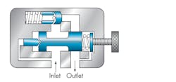
These normally closed valves are primarily used to maintain a set pressure in part of a circuit, usually to counterbalance a weight or external force or counteract a weight (such as a platen or a press) and keep it from free-falling. The valve’s primary port is connected to the cylinder’s rod end, and the secondary port to the directional control valve (Fig. 8). The pressure setting is slightly higher than that required to keep the load from free-falling.
8. Counterbalance valves stop flow from its inlet port to its outlet port until pressure at the inlet overcomes adjusting spring force. An integral check valve permits free flow through the valve in the opposite direction.
When pressure fluid flows to the cylinder’s cap end, the cylinder extends, increasing pressure in the rod end, and shifting the main spool in the counterbalance valve. This creates a path which permits fluid to flow through the secondary port to the directional control valve and to reservoir. As the load is raised, the integral check valve opens to allow the cylinder to retract freely.
If it is necessary to relieve back pressure at the cylinder, and increase the force at the bottom of the stroke, the counterbalance valve can be operated remotely.
Counterbalance valves are usually drained internally. When the cylinder extends, the valve must open and its secondary port is connected to reservoir. When the cylinder retracts, it matters little that load pressure is felt in the drain passage because the check valve bypasses the valve’s spool.
Counterbalance valves often use a pilot signal, usually from the inlet of the actuator, to assist in opening the spool. This assist makes the valves more efficient, and reduces the horsepower requirement and heat generation within the system.
This article is excerpted from the Fluid Power Handbook & Directory. For more information on pressure control valves, please refer to the eBooks posted on our website. Fluid Power Basics contains additional information on pressure-control valves, and Fluid Power Circuits Explained covers the application of various pressure-control valves in useful circuits.
About the Author

Leaders relevant to this article:
