Meeting demands in die casting
It’s hard to beat die casting for spitting out metal components rapidly and with consistent quality. The challenge comes in achieving both simultaneously. For machines powered by hydraulics, this requires precise control of speed and position for high throughput, and tight pressure control for consistent quality. Atos Spa, Sesto Calende, Italy presents a solution to these challenges with their servo-quality proportional valves and digital controllers.
A three-phase process
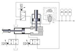
The injection molding process consists of three phases (see schematic). Phase 1 begins with low-speed (0.01 to 0.1 m/sec) motion control of a piston plunger to fill the injection chamber and bleed air from the molten alloy. Meter-in flow control is accomplished with digital proportional cartridge valve A, while digital proportional cartridge valve B is just slightly open to maintain meter-out backpressure.
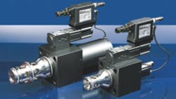
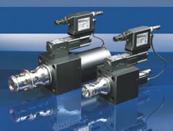
The cartridge valves’ main poppet slides in a sleeve and is hydraulically operated in closed loop through a servoproportional pilot valve on its cover. Integral digital electronics perform double position closed loop control of the poppet and of the pilot spool through integral LVDT transducers.
Key to the high speed of the machine is the high flow capability of the valves — up to 10,000 lpm — coupled with their quick response of 15 to 30 msec from fully open to fully closed. They are available in ISO 7368 sizes 16 to 100.
Phase 2 then commences with high speed (8 to10 m/sec) injection of the molten alloy by the plunger, which can achieve acceleration of 900 m/sec2. The injection motion profile is executed with closed-loop position and speed control by the digital proportional cartridge valves A and B.
Phase 3 begins high pressurization of the molten alloy into the die as the metal solidifies to compensate for shrinkage and to control porosity. This pressure regulation is accomplished with a hydraulic pressure intensifier. Fluid is provided by a bank of accumulators through on-off cartridge valve D and digital proportional control through cartridge valve C.
Valve C’s pilot valve has a single proportional solenoid with spool sliding in a sleeve to improve positioning accuracy and response. Its performance approaches that of a servovalve, but with the durability of a proportional valve.
Component features
Digital drivers use software with adjustable “PID actions.” These allow adjusting valve dynamics to any specific working condition and application. Four sets of PID parameter configurations are available and can be executed in real time during a press cycle. A linearization function permits modifying valve regulation characteristics to improve, for example, metering accuracy under low flow conditions.
Windows-based software from Atos communicates with CANopen, Profibus DP, or Powerlink interfaces for programming valve parameters, diagnostics, and to manage the valve in real time during machine operation.
High acceleration of high-inertial masses during the injection phase are inherent to large die casting operations. These can cause high mechanical shock (up to 50 G), which can compromise the operation of proportional valves. However, Atos designed the proportional valves to withstand these conditions by incorporating structural reinforcement of the most critical components, such as LVDT position transducers and onboard electronics. In addition, a shock absorber plate fitted between the valve’s driver shell and transducer housing reduces vibrations transmitted to the to electronics by about 10 times.
This information was provided by Roberto Fardini, of Atos Spa. For more information, visit www.atos.com.


