Inductance proved to be the culprit
Solutions to problems in the field often are clouded by the fact that the user has changed out several components to get his equipment working again, and no one is sure which one or combination was really at fault. The symptom was treated rather than the root problem because that was the expedient solution. This report covers the opposite situation, one where an OEM wanted to work closely with a valve supplier — my company — to determine the exact cause of a problem and establish a plan to correct it. The OEM’s problem involved a power-shift transmission in which an on/off type solenoid was blamed for occasional sluggish and rough shifting.
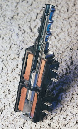
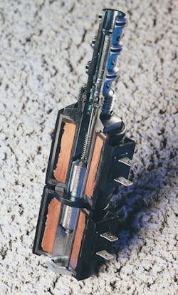
Many powershift transmissions on off-highway construction equipment are controlled by electrohydraulic valves. When this OEM first came to us, they were particularly concerned about whether the coil could provide sufficient force to actuate the valve under all combinations of operating parameters. We selected a standard valve that we believed would perform in this application and tested it against the OEM’s specifications. After we proved to ourselves, and the OEM, that the valve was a viable candidate, the OEM did substantial additional testing before placing an order. Everyone was satisfied with the performance of the valve in the field, and no problems were encountered for the next four years.
Then, in January of 1996, there was a small epidemic of shifting problems, so the OEM asked us if our processes had changed. We reviewed our end-of-line SPC test data, and it did not show any change in valve performance. After we both eliminated some fairly obvious possible causes of the problem without curing it, we agreed to work together to determine the source.
We learned that the shifting problem occurred not only in the field, but also on machines being assembled at the OEM’s plant. We went there to observe the situation, and we saw for ourselves that the clutch definitely hesitated when shifting from high to low gear, and that the hesitation was worse in the morning, when machines were cold. The shop people had identified the solenoid valve as one possible cause, and they dealt with it by simply replacing the entire unit with a new one. After doing this, the transmission shifted properly.
The OEM had originally purchased our valve with 12-V coils, but in late 1994 they switched to a 24-V system. At that time they again questioned whether the coil would supply sufficient force at their new voltage. We replied that the force level should be the same — as would be the case of any solenoid design. They accepted our answer without any further testing.
Neither party considered the coil change significant. Certainly, if there is sufficient power to operate the valve, it should shift. But this is true only if the change in coil inductance does not come into play. The number of turns of wire on a 24-V coil is twice that of the 12-V coil. This increases the inductance by a factor of four.
Until the time of this investigation, we had not considered how the valve behaved with the OEM’s controller. We were told it was a simple switching device with solid-state relays on the ground side of the solenoid. We assumed there was some type of internal diode to protect the controller from back-EMF, but we did not anticipate that the controller would emulate a resistor and/or capacitor network. Capacitance could extend the time to dissipate current in the coil being de-energized, and that is exactly what was happening.
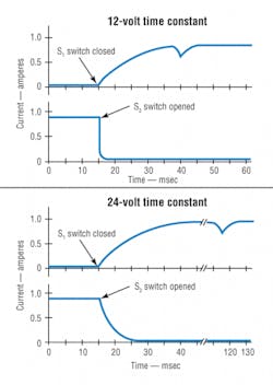
The plots of the 12-V and 24-V time constants as the bottom coil is de-energized and the top coil is energized simultaneously indicate the problem. At 12 V, the current in the S2 coil dissipates in less than 4 ms. The dip or valley shown in the S1 characteristic indicates that the armature has moved completely to the S1-energized position. These characteristics should be typical of any on/off-type solenoid.
However, at 24 V, the current in S2 dissipates over approximately 16 ms because of the controller’s inductance. The current in S2 must fall below 100 mA before the return spring can overcome the magnetic force produced by residual magnetism and trickle voltage. At the same time, the top-coil current should not reach 500 mA before the armature begins to return to neutral. If it does, it will produce a force at the S2 end of the armature that will delay shifting. (This is true when the polarities of the two coils are connected identically.) When this occurs, the dip in the S1 characteristic appears 80 ms after the one recorded with the 12-V system. This delay caused the hesitation in the shifting of the transmission.
We found that several factors had to be present simultaneously for this time delay to occur:
•a resistor/capacitor network must be in the circuit
•the coil temperature must be below room temperature to lower the coil resistance so that more current than normal will be drawn
•the working force of the return spring must be at the low end of the design tolerance, and
•the terminals of the coil must be wired with the same polarity.
All these conditions were possible on the OEM’s transmission application. If any one was not present, the valve would shift as expected, even if the other negative factors occurred.
As a cost-effective field fix, the OEM suggested changing the polarity of the wiring harness for one of the coils. Changing the polarity works because the magnetic field reverses polarity as well. This forces the magnetic field of the opposing coil to collapse as quickly as the 12-V characteristic. Finally, the return spring can overcome the magnetic force induced by any trickle voltage left on the line to move the armature into the neutral position.
The root cause of the failure was identified as an unforeseen interaction between the controller and coil design. If the OEM or HydraForce had a full schematic of the controller or even an in-depth conversation with the controller supplier, the problem might have been avoided.
Today, OEM design engineers have to consider coil inductance for simple on/off solenoids as well as electrohydraulic proportional valves. The lesson learned: communication must be on-going between all involved in system design, implementation, and changes.
Tony Casale is senior design engineer at HydraForce Inc., Lincolnshire, Ill. for more information, call (847) 793 2300 or email [email protected].About the Author

Leaders relevant to this article:


