Hydraulic-Electric Analogies: Transmission Comparisons, Part 3
This file type includes high-resolution graphics and schematics when applicable.
Continuing with the analogy that a pump is to the hydraulic circuit what a generator is to an electric circuit, the ideal generator is likewise 100% efficient. A real generator has two sources of internal losses. First, some amount of resistance always exists in the windings that make up the armature and field because they consist of wire, which has resistance. Second, inevitable friction and windage losses occur that accompany any part in motion.
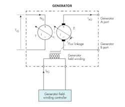
The analytical schematic of the ideal, loss-free, shunt-connected dc generator is depicted in Fig. 7. The term shunt means there is a bypassing of current. More specifically, though, the armature current and the field current in the shunt-connected machine are independently affected and controlled.
As a matter of review, the generator uses a coil that spins in a magnetic field to generate a voltage. That field is created by the field winding, which is stationary. The rotor, normally called the armature in a generator, is the spinning part. It, too, incorporates a multi-turn, multi-segmented winding, and its spinning motion in the magnetic field results in an induced voltage per Faraday’s law.
The rotor-mounted commutator carries the internally generated voltage to the outside world. The commutator is in physical, sliding contact with the stationary brushes. The brushes, shown as small black rectangles on the electrical side of the schematic, are usually made of graphite, which provides conductivity. Graphite also has natural dry lubricity to minimize the wear rate due to the necessary relative motion between the commutator and the brushes.
While an alternating current circulates inside the armature coil, the commutator and its contacting brushes are positioned so that the resulting current in the outside world is unidirectional. In other words, it is direct current. This makes the brushes and commutator perfectly analogous to the port plate and its kidney ports in the hydraulic pump. The brush-commutator effect and the port plate-kidney port effect both provide the necessary conversion from internal ac to external dc in their respective machines.
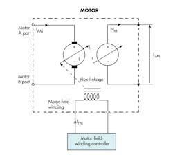
For purposes of comparison, the analytical schematic for a shunt-connected dc motor is shown in Fig. 8. The diagram is useful for reviewing the operation of the mechanical and electrical sides of the machine.
It works as follows: A motor generates torque because of the forces that act on the current-carrying armature conductors mounted on the rotating body. However, because those conductors spin in the stationary magnetic field, there has to be an induced voltage. So, two things are going on at the same time. The same parts that create the torque also create the voltage.
Electromotive Force
The induced voltage always acts in a direction against the applied external voltage (not shown in the accompanying figures), but connects to the A and B ports in Fig. 8. The applied voltage, be it a battery or dc power supply, will create a current in the direction shown as IAM in Fig. 8. That current will result in a torque, causing the armature to accelerate.
At the same time, the moving coil on the armature has a voltage induced that fights, or opposes, the applied external voltage. As the shaft speed increases, the counter voltage, often referred to as counter electromotive force (counter emf), reduces the motivating current, IAM. Eventually, the counter emf rises to equal the applied external voltage, causing the current to drop to zero. There is no more torque, so the motor stops accelerating.
At this condition, it will have reached its steady-state speed. That is, the motor accelerates until the counter emf equals the applied voltage. Thus, the applied voltage controls the ultimate speed. In an ideal machine, this explanation is 100% true. However, in a real machine with its all-but-assured inefficiencies, it is only approximately true.
The described dc machine—whether motor or generator—will have an analytical schematic with a mechanical part (torque and speed) and an electrical part (voltage and current). A constant energy exchange takes place in the two analytical generators (the circles in Figs. 7 and 8).
To understand this fundamental principle, consider that the motor is operating at its no-load speed and the input current, IAM, is at or near zero. Some external load is then applied (an external mechanical load is applied that needs torque to turn it), requiring output power from the motor. The shaft slows down, reducing the counter emf, and results in a rise in input current. The motor then comes to a slower steady-state speed.
The input power increases to meet the needs of the load. With this energy exchange, the electrical input circuit “knows” what is going on in the output circuit. Likewise, if the input electrical quantities are changed, we may conclude that the output circuit “knows” what is happening at the input. It is simply a case of classical energy conversion from electrical to mechanical. Power out equals power in—at least that’s the case if we could actually build ideal machines.
The input rises and falls as the output demands rise and fall. The same interchanges take place in the generator. A perfectly analogous process occurs in the hydraulic pump and motor: When a pump is operating at some steady-state input speed and torque, and then the outlet pressure is bumped up, it increases the pump input torque, and possibly decreases the speed of the prime mover. In addition, the input mechanical power rises to meet the hydraulic power needs at the output.
Again, the input “knows” what is happening at the output and vice versa, providing classical energy conversion and conservation. Two simple equations characterize the ideal generator and motor, which could be seen as perfectly analogous to those of the ideal pump and motor.
The counter emf is:
E = (2 π /60) kmg× IF× N
where E is the generated counter electromotive force, V; kmg is a constant to convert the product of field current and speed to voltage; IF is the field current, a; and N is the shaft speed, rpm.
The torque expressed as:
T = kmg× IF×IA
where T is the shaft torque, N-m; kmg is a constant to convert the field and armatures current to torque; and IA is the armature current, a.
Analytical Schematics of Practical Generators and Motors
As with hydraulics, ideal electrical machines exist only as models. Electric motors and generators have internal losses analogous to those of hydraulic pumps and motors.
Because hydraulic pumps are positive-displacement machines (flow sources, not pressure sources), hydraulic losses consist of parallel internal leakage paths that divert some of the displaced fluid that would otherwise reach the output work port. In contrast, the electrical losses are in series and serve to resist (impede) the current that enters and leaves the motor or generator. The result is a voltage drop, whereas hydraulic pumps and motors experience flow losses. Of course, both suffer from frictional losses. All losses contribute to the machines’ inefficiencies.
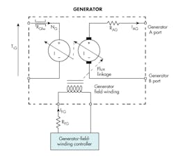
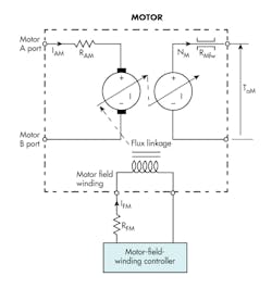
This leads to analytical schematics that include the frictional and electrical resistance loss elements as depicted in Fig. 9. The mechanical friction is represented by the same symbol shape as that used in the pump and motor, RGfw. The armature resistance, RAG, occurs in series with the armature, and field resistance is represented by RFG. The G in the subscripts indicates that it applies to the generators. The three resistances are called parasitic effects because, like parasites, they come with the wire that is used to make the coil’s windings.
The value of the armature resistance is a bit complicated because it includes the effects of the inevitable eddy currents that circulate in the iron laminations of the armature and stator. To complete the schematic picture for practical electrical machines, the analytical schematic for the electric motor is added (Fig. 10). It is the mirror image of the generator with its three loss elements: mechanical friction, armature resistance, and field resistance. In this case, the subscripts contain M to indicate its application to a motor.
