Thermal Analysis of a Garbage Truck’s Hydraulics
A characteristic sometimes overlooked with hydraulic systems on industrial trucks, such as garbage trucks, is what happens when they operate at high fluid temperature. High fluid temperature can degrade the fluid, cause premature failure of components, rob system performance, and even pose safety hazards to personnel.
A finite-difference model for a typical garbage-truck hydraulic system was derived to predict these temperatures. Actual weather data for a sea-level southwestern American city in mid-summer were used as input parameters for the model to represent actual worst-case conditions. This model considered pressure losses in the hydraulic system from viscous effects and friction during operation. These losses increase internal energy of the fluid, resulting in higher fluid temperature. The model also incorporates calculation of heat transfer to and from the hydraulic system. The system receives solar radiation and expels heat by convection to the ambient air.
The model predicts fluid temperatures of up to 300° F during normal operation of each truck on a day when the ambient air temperature reaches 115°F. The 300°F temperature produced by a garbage truck under such conditions significantly exceeds the maximum recommendation of 180°F for hydraulic fluid. The conservative model also tends to underestimate pressure loss and thermal parameters that predict fluid temperatures. Actual fluid temperatures for the given meteorological parameters will be higher than those in the model output.
Building the Algorithm
The algorithm in the model was based on the first law of thermodynamics, which states that the heat transferred to a system equals the sum of the increase in internal energy of the system and the work done by the system. If we consider hydraulic fluid to be incompressible, its specific heat is well documented. The product of the fluid’s specific heat and the increase in its temperature yields the increased internal energy of an incompressible fluid. Therefore, we can calculate fluid temperature if we know the initial fluid temperature and the temperature change, which is determined by evaluating the heat transferred to or from the system and the work done by or on the system.
Heat transfer evaluated by the model includes solar radiation into the hydraulic system and convection of heat from the system to the ambient air. Solar radiation data were obtained from a state meteorological database for a day when the ambient temperature reached almost 115°F. These data give the amount of solar energy incident on a horizontal surface by hour of the day. We estimated that the hydraulic system absorbs 80% of incident radiation, based on documented emissivities of similar materials.
Both free convection and forced convection were evaluated as mechanisms for transferring heat from the hydraulic system to the air. Free convection is a process in which molecules of a fluid (ambient air in this analysis) in contact with a warmer body absorb heat, become buoyant, and are displaced by molecules with less internal energy. For the sake of simplicity, we assumed that no temperature gradient exists between the hydraulic fluid and the ambient air and that the wall temperature matches that of the hydraulic fluid.
In reality, the walls of hydraulic reservoirs, hoses, and other components tend to absorb heat from the fluid. Therefore, wall temperatures are actually lower than the fluid’s, creating an insulating effect. The heat transfer rate varies directly with the difference between the wall temperature and the temperature of the air, so the actual heat transfer rate from the fluid to the ambient air by free convection will be less than that estimated by the conservative model.
More on Convection
Forced convection occurs when a fluid (ambient air) is directed at some non-zero velocity against a warm surface. Heat is transferred by a combination of buoyant effects and momentum as energy from the warm surface by conduction to molecules of air. These molecules are then replaced by other molecules lower in internal energy. Wind promotes forced convection. Meteorological data for a sea-level southwestern U.S. city were inspected, and it was found that the maximum wind speed for many days stayed less than 8 mph during the hours of operation for the packer trucks.
In keeping with a conservative approach, we assumed that the wind blew directly across the hydraulic system and reservoir in the direction most beneficial for cooling the system. Furthermore, the outer wall of the reservoir is partially exposed to ambient air as the truck is driven. An average effective wind speed of 12.5 mph (relative to the reservoir) was calculated, based on the estimated truck speed and portion of the day during which the truck was moving. Forced convection of heat from this surface was calculated based on the higher effective wind speed. Because the rate of heat transfer varies directly with wind speed, these choices for wind speed values are conservative. As in the free convection analysis, wall temperatures were equated with hydraulic fluid temperature.
Pure conduction of heat from the hydraulic system and reservoir to another solid body was not considered a significant mechanism for cooling because the contact areas are small and because other nearby bodies are also heat sources (the truck engine and exhaust). Conduction between solid bodies is proportional to the contact area and the temperature difference. Radiation and convection of heat from the road surface to the hydraulic system and reservoir also were not considered because of the difficulty in describing these mechanisms mathematically and because assuming them to be negligible is conservative.
Components of the Hydraulic System
The hydraulic pump in these trucks is driven through a power takeoff (PTO). The difference between the input power from the PTO and the work performed by the hydraulic cylinders becomes pressure losses as the hydraulic fluid flows through the circuits. Empirical data relating pressure loss to fluid flow rate for different types of hose and tube are available in the literature.
Hose sizes were taken from the specifications for an actual side-load compactor truck, and pressure losses were obtained from these data. Pressure losses for pipe and standard fittings (elbows, tees, sudden expansions, sudden contractions) are related to fluid velocity, density, and viscosity and are proportional to empirical factors reported in literature. The sizes of pipe and fittings were obtained from drawings, and losses were tabulated after calculations were made using this information.
Pressure losses through filters, hydraulic control valves valves were obtained from the actual manufacturers’ technical catalogs for each model. Properties of a typical hydraulic fluid recommended for use in such climates (Texaco Rando HD46) were obtained from literature published by Texaco for that fluid.
Setting up the Analysis
Perfect data cannot be obtained for any analysis. In cases in which directly applicable data for refuse truck specifications, drawings were not available, or calculation of input parameters or data was not straightforward, we made assumptions that could be reasonably supported. When no reasonable assumption could be made, data that would lead to higher predicted fluid temperatures were not used, in order that the analysis remain conservative.
We assumed that the packer trucks operate on a 10-hour daily shift. The actual time each truck is collecting (and, therefore, operating the hydraulic system’s boom and pack circuits) is approximately six hours per day. The pack circuit is continuously operating while the truck is collecting, then is turned off when the truck is driven to and from a landfill, transfer station, or fleet garage.
The boom operates intermittently while the truck is loading cans at a house. It is then inactive when the truck is driven between houses. Based on discussion with waste management personnel, it was determined that each truck collects solid waste from 1,200 to 1,300 houses per day. Using these parameters, duty cycles were evaluated for the boom and pack circuits and were applied by the model to the calculation of pressure losses because no pressure losses occur when the hydraulic system is not actuated. However, heat transfer occurs continuously.
For much of the time, the pack circuit is actuated, but the boom circuit is not. During these times, the model calculates no losses for the boom circuit. However, hydraulic fluid is still flowing through the control valve for the boom circuit and back to the reservoir, although no fluid flows through the work port on the control valve. In reality, though, some pressure loss from this flow still occurs when only the pack circuit is actuated. Omitting this loss tends to underestimate fluid temperatures and is conservative.
Examining the Results
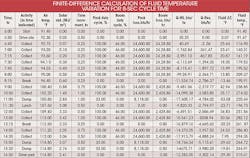
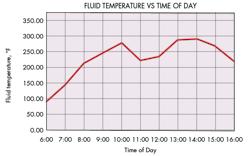
The finite difference model was run for three cycle times: 8, 10, and 14 seconds. Actual cycle times usually range from 10 to 14 seconds. The table above shows detailed results for the 8-sec cycle, whereas the graph below summarizes fluid temperatures during the day for a 10-sec cycle. The analyses account for the normal activities of the truck and operators during a typical shift, including driving to pickup sites and back to the collection yard, collecting refuse in residential neighborhoods, break times, lunch time, and refuse dumping.
This scenario of activities is proposed as typical based on our experience for daily collection operations. It undoubtedly varies from day to day and from truck to truck. We don’t expect these variations would alter the conclusions for this analysis. Solar radiation as energy incident on a horizontal surface per unit time was obtained for a southwestern U.S. city for the subject day and is shown on the table.
The time increments shown generally conform to the operational activities for the truck, except in the early hours, where time increments were reduced to promote accuracy in exercising the model. During this early period, the thermal dynamics of the system are changing rapidly because the hydraulic system is starting to transfer energy to the fluid, and more data points are needed.
The columns labeled Pack loss and Boom loss represent the energy put into the fluid by the pressure drops in the pack-eject and boom circuits, respectively. The columns labeled Q-HS and Q-Res are the total rates of heat transfer from the hydraulic system (excluding the reservoir) and the reservoir, respectively, for all heat transfer mechanisms—solar radiation, free convection, and forced convection.
The last two columns show the change in fluid temperature from the last time period and the fluid temperature for the indicated time period, respectively. The model calculates the change in temperature due to the energy input to the fluid, less the heat energy transferred from the fluid, during the prior time period and adds the temperature difference to the fluid temperature for the last time period to obtain the value shown.
The table shows that the temperature of the modeled fluid exceeds 180°F early in the day. Operator breaks and down time at the dump/transfer station promotes cooling because convection removes heat from the hydraulic system and no pressure losses are produced. However, internal energy is generated at such a high rate from pressure losses in the system during operation that the fluid remains at excessive temperatures for almost the entire day because the heat transfer rate from the fluid is insufficient for cooling it.
Effect of Heat on Seals
Standard seal materials for normal industrial applications have maximum allowable temperatures to 250 or 300° F, depending on the actual compound. For most of these, temperatures from 250 to 300° F are allowable for only brief periods. For Buna-S, the temperature range goes to 225°F. (Higher-cost Viton seals can sometimes be specified for hydraulic components, but the maximum temperature for Viton is only 250°F.)
This analysis indicates that fluid temperatures higher than 300° F can be expected on hot days in such climates. This means that seals in the hydraulic components should be expected to soften during operation of the packer trucks. As the seals soften, they will tend to extrude into the space between the parts they are sealing and, eventually, break. Hydraulic fluid would begin leaking when the seal extrudes, and possibly catastrophic leaks would likely occur when a seal breaks.
However, the deleterious effects of high temperature degrade more than just seals. It also degrades the hydraulic fluid. Data for Texaco Rando HD 46 were used as a typical fluid for use in such hydraulic systems. Texaco’s literature for this fluid shows properties up to a maximum temperature of 180°F. Literature for similar fluids of the same grade indicate operating ranges for No. 46 grade fluid of 32° to 160°F.
Parker Hannifin Corp. recommends a maximum reservoir fluid temperature of 145°F. Higher temperatures can produce oxidation products (varnish), which can clog orifices, corrode metal surfaces, form sludge, and cause rapid wear of metal parts.
Peter J. Weller, P.E., is a consulting mechanical engineer providing engineering and design services to industry and expert testimony services. For more information, visit www.peterjweller.com.
About the Author

Leaders relevant to this article:


