Low-speed/high-torque motors
Download this article in .PDF format
Low-speed/high-torque (LSHT) motors are one of the more cost-effective and dependable parts of a hydraulic system. They offer a designer many advantages over a system comprised of a high-speed motor and a gearbox speed reducer. Foremost is the fact that LSHT motors transmit a large amount of power from a comparatively small drive envelope. Low noise and vibration and high energy efficiency can be additional benefits. Rapid reversal of direction may be achieved simply by reversing the direction of hydraulic fluid flow. LSHT motors also exhibit smooth starting torque.
Maximum shaft speed for LSHT motors can range up to 1,000 rpm, and some motors operate smoothly at speeds as low as 0.1 rpm with suitable closed-loop electronic control. These motors generally exhibit good starting efficiencies and fairly constant torque over their entire speed range.
LSHT motors come in such a wide variety of designs that direct comparison of performance between two types is virtually impossible. Instead, here are some important points about four of the main LSHT motor styles:
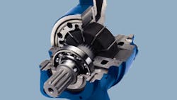
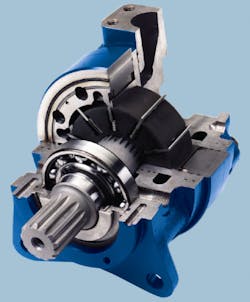
Vane motors - These motors, Figure 1, resemble traditional hydraulic vane motors, in which pressure (assisted by springs) pushes against a series of vanes. These vanes ride a ring cam and slide in and out of rotor slots. The vanes form sealed chambers, which carry fluid from an inlet to an outlet. LSHT vane motors run most efficiently at lower pressures and are radially balanced, which extends their operating life. Because of a fairly large number of leakage paths, they tend to have lower volumetric efficiency at slow speeds. Displacements of up to 650 in.3/rev are available.
Rolling-vane motors - This design offers a nearly constant volumetric efficiency at all speeds. The rolling vanes function as timing valves, sequencing the fluid flow to ensure high pressure against trailing surfaces and low pressure against leading surfaces. These motors have a somewhat limited displacement range and, like vane motors, cannot tolerate cavitation. They are radially balanced, as pressurized fluid always acts on equal and opposite areas.
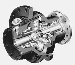
Piston motors - There are several different designs that fall under this category. Generally, radial-piston motors have a large displacement range. Leakage-resistant characteristics - and hence, good volumetric efficiency through the entire speed range - characterize eccentric drum radial piston motors. This style of motor has a high starting torque and is very efficient in the medium- to high-displacement range. Motors known as cam-type radial-piston motors, Figure 2, are slightly less efficient because of their concentric configuration.
On both of these types, the manufacturers speed recommendations must be followed closely. Low speed may bring about torque ripple or speed flutter. These motors use pistons in several cylinders to push down on an off-center throw of a crankshaft drum. At the same time, other cylinders allow oil to escape through their valves to the tank drain port. The cylinders work slightly out of phase so that no dead spots are created at top dead center.
Axial piston motors have good volumetric efficiencies, especially at lower pressures. Good starting torque characteristics are also inherent to this design.
Finally, axial-ball-piston motors have multiple wave cams that are pressure balanced to operate without vibration or pulsation. They are similar to a cam design in this regard. Because operating clearances around the balls are small, volumetric efficiency is often very good.
Gear motors - Gear motors are very economical, but often have lower volumetric efficiencies due to higher leakage rates. These motors are best suited for low-pressure applications.
External-gear motors consist of one gear connected to an output shaft, and a matched idling gear. Fluid entering the housing forces the gears to rotate, and exits through the opposite side of the motor.
Internal-gear motors have an inner and outer gear set within the housing, with the inner gear having fewer teeth. Both of the gears rotate as fluid flows through the motor. The center point of the inner gear coincides with that of the output shaft. The distance between the center of rotation of the inner and outer gear is known as the eccentricity.
Construction
There are many variations among basic LSHT motor designs. The following are representative:
Gear motors usually are of Gerotor design and consist of a Gerotor set, a splined drive coupling, and a commutator valve. The Gerotor set has a stationary outer ring which is part of the motor housing, and a rotor. The outer ring has integral gear teeth which mesh with mating teeth on the rotor. The rotor has one less tooth than the outer ring. A 6-lobe/7-lobe gear set has a 6:1 mechanical advantage. Pressurized fluid forces the rotor to revolve inside the outer ring while orbiting around the center of the outer ring. A coupling transmits the motion of the rotor to the output shaft. Each tooth of the rotor is in sliding contact with the outer ring at all times.
The commutator valve, connected to and rotating with the output shaft, routes pressurized fluid to the spaces between the gear teeth. Pressure and return passages in the commutator valve are connected to the motor ports through the housing. As a valve rotates, the fluid passages which keep the pressurized fluid in phase with the opening and closing of the spaces between the gear teeth are subject to pressurized fluid, three are connected to the return line, and the seventh is blocked. The motor is bidirectional, depending on which port is pressurized.
Models for heavy-duty applications, and those which require higher shaft load capacities, use precision-machined rollers to form the displacement chambers. The rollers provide support and rolling contact to minimize friction as the inner gear rotates.These motors generally are referred to as geroller motors.
Vane motors resemble traditional hydraulic vane motors, Figure 1, where vanes ride a ring cam and slide in and out of rotor slots. The rotor is independent of the ring and is centered by a shaft. The rotor puts only pure torque into the shaft. There are no side loads.
Rolling-vane motors have fluid flow through the motor body to the rotor shaft through a combined body-and-shaft groove. Passages within the rotor shaft route high-pressurized fluid radially into pressure chambers; symmetrical passages route low-pressurized fluid back through the rotor shaft and body to the outlet port. The rolling vanes function as timing valves to sequence the fluid to insure that each pair of rotor vanes always has high pressure against its trailing surface, and low pressure at its leading surface. Because the pressurized fluid always acts on equal and opposite areas, the rotors are always in hydraulic balance.
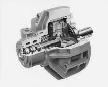
Radial-piston motors have a great variety of designs within the basic radial configuration. For example, one design of this type motor produces hydraulic thrust on a crankshaft that produces output torque, Figure 3. The hydraulic load on the piston crown is transmitted to the connecting rod through a passage to a pressure-compensated hydrostatic bearing. This creates a high-pressure column of oil which is trapped in a relieved area of the connecting rod foot. The trapped static oil column transmits piston force to the crankshaft with only a small percentage of the load being carried on the connecting rod foot.
As system pressure increases, pressurized fluid trapped in the connecting rod pocket increases, automatically compensating for increased piston loading and keeping the percentage of mechanical loading constant at a low level.
The radially mounted pistons in motors of another design reciprocate inside bores in a stationary cylinder housing and are connected to rollers that bear on a cam ring. A rotary valve distributes pressurized fluid to each cylinder in sequence. Fluid pressure pushes the pistons outward, forcing the rollers against the cam ring, causing it and the outer casing of the motor to rotate. Fixed side guides absorb reaction forces on the rollers, "unloading" the pistons from any tangential forces.
A two-speed valve that attaches directly to the motor with no intermediate plumbing permits operation at two different speeds without changing flow to the motor. In the higher speed range, the torque is halved.
A third design also produces thrust on an eccentric crankshaft through connecting rods, a heat-treated ring, and spherical roller bearing. The ring follows the turning crank without rotating itself. Since there is no friction between the ring and the connecting rod shoes, hydrostatic balancing is not necessary. The seven pistons have a working frequency of three and four; before the first of the three pistons under pressure reaches the top of its stroke, a fourth piston pressurizes to smooth rotation at low speed.


