Hydraulic-Electric Analogies: Power Sources, Part 1
Hydraulic pumps and motors, and electrical generators and motors, have been introduced in earlier discussion, but they all deserve more attention regarding their remarkable similarities as well as their differences. In short, appreciating their analogies requires further discussion. In some ways, it’s uncanny how similar hydraulic pumps and motors are similar to electrical generators and motors. Yet, aside from the obvious differences in their relative powering media, they differ significantly in other ways.
This file type includes high resolution graphics and schematics when applicable.
Power Converters
Power converters are the devices (e.g., generators and alternators) that change mechanical power into electrical power or convert it electrical power to mechanical, as in the case of electric motors. Similarly, pumps convert their mechanical input power into hydraulic output power, and hydraulic motors convert hydraulic power to the mechanical domain. Generators and alternators are analogous to hydraulic Likewise, linear motors and rotary solenoids are analogous to hydraulic cylinders and rotary actuators, respectively.
The foremost, yet often-forgotten, advantage of hydraulic machinery is how easy it is to achieve linear motion, using a device as simple as a cylinder. In kind, the often-forgotten advantage of electrical machinery is the ease in achieving rotary motion. Virtually no machine is simpler, at least in principle, than an induction motor. Like the hydraulic cylinder, the induction motor has only one moving part. In fact, the perfect analogy to the hydraulic cylinder would be the induction motor, were it not for their differences in output motion, i.e., linear versus rotary motion.
A hydraulic rotary actuator with its single moving part might be a more perfect analogy to the induction motor, except for the former’s inability to provide unlimited rotational angular motion. Indeed, the rotary actuator provides rotational output, and does so with only a single moving part, at least in one of its incarnations. In contrast, achieving linear output motion with electrical machines requires rotary-to-translational motion, such as lead and ball screws, which have reliability and loading limitations.
On the other hand, high-pressure hydraulic pumps, notably piston types, are complex machines with many inner parts that must be manufactured to very exacting tolerances. Nonetheless, piston pumps and motors have advanced significantly, offering proven reliability in spite of their construction and design intricacies. Many of these issues will be covered in future articles, starting with details on electrical power-conversion machinery.
Electrical Power Conversion
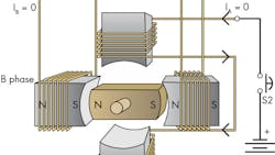
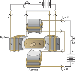
This discussion begins with the principle parts of an alternating-current synchronous motor. Alternating-current machines are simpler than direct-current machines. Figure 1 shows the essential ferromagnetic parts of a two-pole, two-phase, synchronous motor. It consists of a permanent magnet, comprising the rotor, mounted on a central shaft to enable rotation. Surrounding the magnet are four stator pieces that will form the ferromagnetic cores of two stationary-voltage and/or current-activated electromagnets. Two opposing core pieces form one phase as well as forming one of the two electromagnets. Therefore, there are two stator pieces for one phase and two stator pieces for the other. Later, the article will show that there are four different magnetic poles, and yet it’s still only a two-pole machine.
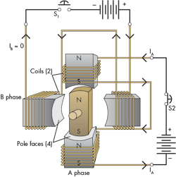
Progressively and electrically exciting each individual magnetic core (electrical exciting coils are added) sequentially will show that the rotor can be magnetically attracted to the excited core and, thus, cause rotation. Figure 2 shows the added coils that form the two separate electromagnets. Batteries are used to illustrate the motor’s operation, and later, ac will be used to excite the coils.
Note first that the switch S2, which is closed, supplies dc current to the vertical magnets, Furthermore, the current that enters the upper coil passes via a jumper wire and enters the lower coil, which is wound so that their respective magnetic fields are in the same direction to one another. The right-hand rule and nature of the windings tell us that the upper parts of both stator pieces are north magnetic poles and their bottoms are south magnetic poles. Consequently, the rotor’s north magnetic pole is attracted to the south side of the upper stator piece, while its south pole is attracted to the north side of the bottom coil. This is an enhancing situation, meaning that the two stator magnets are both acting to keep the rotor in the electrical position shown.
In addition, note that S1 is open, which means no current is delivered to its coils. Thus, the coils contribute nothing to the positioning of the rotor. Their stator pieces are shown with no magnetic poles.
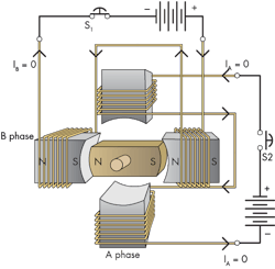
In Figure 3, S2 has been opened, which de-energizes the vertical coils while S1 is closed and excites the horizontal coils. With no vertical magnetic field in the presence of a horizontal field, the rotor naturally snaps into the 9 o’clock position as shown.
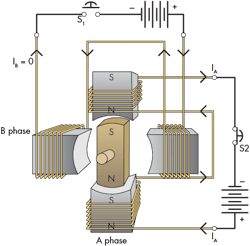
This general process continues in Figure 4. Here the switch, S1, was opened, cutting current to the vertical coils. At the same time, the battery for the vertical coils has its polarity reversed and switch, S2, is closed. The current through the vertical coils will be reversed, which in turn reverses the magnetic polarities. At first glance, Figure 4 may appear the same as Figure 2. However, a closer look reveals that all of the poles are reversed along the vertical axis. The rotor now has turned a total of 180°.
One additional step in this progression will turn the rotor another 90° (Fig. 5). Again, after only a quick glance, Figures 3 and 5 may seem to be the same; however, the magnetic polarities are reversed as in the earlier case. By properly sequencing the opening and closing of the switches and changing the battery polarities, the rotor can be made to progress through one complete revolution. The next logical step is to return to the starting conditions shown in Figure 2, enabling the motor to rotate continuously. It just requires the proper switching action.
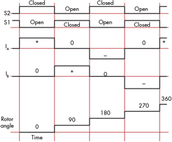
A sequential timing diagram keeps track of events that must follow in a specific order. Figure 6 provides a diagram of the events described above. It’s important to be aware that the current, IA, is controlled by S1 and IB is controlled by S2. Notice how the graph indicates the switching of the batteries by showing a positive value for IA in the 0° interval, but a negative value in the 180° interval. We can see in the current that this is really a two-pole machine because the currents require 360° of shaft (rotor) rotation to get through one complete mechanical cycle. Also, bear in mind that the terms “open” and “closed” are used in the electrical context—closed is conducting, open is blocked.
This file type includes high resolution graphics and schematics when applicable.
