Engineering Essentials: Hydrostatic Transmissions
The operating principle of hydrostatic transmissions (HSTs) is simple: A pump, connected to the prime mover, generates flow to drive a hydraulic motor, which is connected to the load. If the displacement of the pump and motor are fixed, the HST simply acts as a gearbox to transmit power from the prime mover to the load. Most HSTs, however, use a variable-displacement pump, motor, or both so that speed, torque, or power can be regulated (Fig. 1).
Depending on its configuration, the HST can drive a load from full speed in one direction to full speed in the opposite direction, with infinite variation of speed between the two maximums—all with the prime mover operating at its optimum speed.
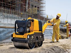
1. Hydrostatic drives pack a lot of power into a small package and allow versatile machine control. The walk-behind compactor shown here uses a dual hydrostatic drive: one to rotate the drum, and one to rotate an eccentric weight, which increases compacting force by nearly 22 kN in addition to the machine's weight.
HSTs offer many important advantages over other forms of power transmission. Depending on its configuration, an HST:
- transmits high power in a compact size
- exhibits low inertia
- operates efficiently over a wide range of torque-to-speed ratios
- maintains controlled speed (even in reverse) regardless of load, within design limits
- maintains a preset speed accurately against driving or braking loads
- can transmit power from a single prime mover to multiple locations, even if position and orientation of the locations changes
- can remain stalled and undamaged under full load at low power loss
- does not creep at zero speed
- provides faster response than mechanical or electromechanical transmissions of comparable rating, and
- can provide dynamic braking.
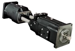
Either of two types of construction is used for HSTs: integral and non-integral. Non-integral construction is by far the most common, because power can be transmitted to one or more loads in areas that would otherwise be difficult to access. In this technique, the pump is coupled to the prime mover, the motor is coupled to the load, and they the pump and motor are connected through hose and tubing assemblies, Fig. 2.
Whatever its task, the HST must be designed for an optimum match between the engine and the load. This allows the engine to operate at its most efficient speed and the HST to make adjustments to operating conditions. The better the match is between input and output characteristics, the more efficient the entire power system will be.
Ultimately the power system should be designed for a balance between efficiency and productivity. A machine designed for maximum efficiency usually has sluggish response, which robs productivity. Conversely, a machine designed for quick response usually exhibits low efficiency because a high degree of energy must be available at all times to perform work—even when there is no immediate need for work.
Four Functional Types of HSTs
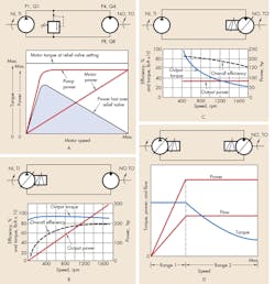
The configuration of an HST—whether it has a fixed- or variable displacement pump, motor, or both—determines its performance characteristics. Figure 3 summarizes these configurations and the performance characteristics of each.
The simplest form of hydrostatic transmission uses a fixed-displacement pump driving a fixed-displacement motor (Fig. 3a). Although this transmission is inexpensive, its applications are limited, primarily because alternative forms of power transmission are much more energy efficient. Because pump displacement is fixed, the pump must be sized to drive the motor at a fixed speed under full load. When full speed is not required, fluid from the pump outlet passes over the relief valve. This wastes energy in the form of heat.
Using a variable-displacement pump instead of one with a fixed displacement creates a constant torque transmission (Fig. 3b). Torque output is constant at any speed because torque depends only on fluid pressure and motor displacement. Increasing or decreasing pump displacement increases or decreases motor speed, respectively, while torque remains fairly constant. Power, therefore, increases with pump displacement.
Using a variable-displacement motor with a fixed-displacement pump produces a transmission that delivers constant power (Fig. 3c). If flow to the motor is constant, and motor displacement is varied to maintain the product of speed and torque constant, then power delivered is constant. Decreasing motor displacement increases motor speed, but decreases torque—a combination that maintains constant power.
The most versatile HST configuration teams a variable-displacement pump with a variable-displacement motor (Fig. 3d). Theoretically, this arrangement provides infinite ratios of torque and speed to power. With the motor at maximum displacement, varying pump output directly varies speed and power output while torque remains constant. Decreasing motor displacement at full pump displacement increases motor speed to its maximum; torque varies inversely with speed, and horsepower remains constant.
The curves in Fig. 3d illustrate two ranges of adjustment. In Range 1, motor displacement is fixed at maximum; pump displacement increases from zero to maximum. Torque remains constant as pump displacement increases, but power and speed increase.
Range 2 begins when the pump reaches maximum displacement, which is maintained while the motor’s displacement decreases. Throughout this range, torque decreases as speed increases, but power remains constant. (Theoretically, motor speed could be increased infinitely, but from a practical standpoint, it is limited by dynamics.)
An Application Example
Assume that a 3,116-lb-in. torque load must be driven at 1,000 rpm with a fixed-displacement HST. Power required is determined from:
P = T × N / 63,024
Where:
P is power in hp
T is torque in lb-in., and
N is speed in rpm.
Therefore,
P = 3,116 × 1,000 / 63,024 = 50
If we choose a 2,000-psi pump (based on experience for providing a good combination of size, weight, performance, and cost) rated at 50 hp, we then calculate the flow it must deliver:
q = 1,714 × P / p
Where:
q is flow in gpm, and
p is pressure in psi.
Therefore,
q = 1,714 × 50 / 2,000 = 43 gpm
We then select a hydraulic motor with a displacement of 10 in.3 /rev to deliver 3,116 lb-in. of torque at 2,000 psi—approximately 43 gpm at 1,000 rpm. Figure 3a shows the power/torque/speed characteristics for the pump and motor, assuming the pump operates at constant speed.
Pump flow is maximum at this operating speed, and the pump attempts to deliver this quantity of oil to the fixed-displacement hydraulic motor. Load inertia makes it impossible to accelerate instantaneously to full speed, so part of the pump output flows over the relief valve. (Figure 3a also illustrates the power loss during acceleration.) As the motor increases speed, it transmits more of the pump’s output, and less oil flows over the relief valve. At rated speed, all oil flows through the motor.
Torque is constant because system pressure builds to the relief valve setting immediately after the control valve shifts. Power lost over the relief valve is the difference between the constant power delivered by the pump and the variable power delivered by the motor.
The area under this curve represents the power wasted when the transmission starts or stops. It also shows the low efficiency for any operating speed below maximum. A fixed-displacement transmission is not recommended for applications requiring frequent starts and stops, or when less than full load torque occurs frequently.
Torque-Speed Ratio
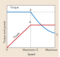
Theoretically, the maximum power a hydrostatic transmission can transmit is a function of flow and pressure. However, in constant power transmissions with variable output speeds, theoretical power divided by the torque/speed ratio determines actual power output. The greatest constant power that can be transmitted is determined by the lowest output speed at which this constant power must be transmitted.
For example, if the minimum speed represented by point A on the power curve in Fig. 4 is half the maximum speed, the torque-to-speed ratio is 2:1. The maximum power that can be transmitted is half the theoretical maximum. At point B, corresponding to output speed A, the torque curve decreases as speed increases. At maximum output speed, it has dropped to point C.
At output speeds less than half the maximum, torque remains constant at its maximum value, but power decreases in proportion to speed. The speed at point A is the critical speed and is determined by the dynamics of the HST’s components. Below critical speed, power decreases linearly (with constant torque) to zero at zero rpm. Above critical speed, torque decreases as speed increases, which provides constant power.
Building a Closed-circuit HST
The descriptions of closed-circuit hydrostatic transmissions in Fig. 3 concentrate on parametric considerations only. Additional functions must be provided to achieve a practical HST.
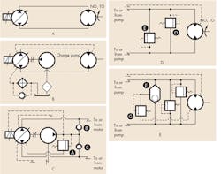
Pump-end components. Consider, for example, a constant-torque HST—the type used most commonly—with a servo-controlled, variable-displacement pump driving a fixed-displacement motor (Fig. 5a). Because this is a closed-circuit HST, slip flow accumulates in the pump and motor cases and is removed through a case drain line (Fig. 5b). The combined case drains flow to the reservoir through a heat exchanger.
One of the most important components in a closed-circuit HST is a charge pump. The charge pump is usually an integral part of the main pump package, but can also be an independent pump gang-mounted with the drive pumps it serves. Whatever the arrangement, the charge pump performs two functions. First, it prevents cavitation of the main pump by replenishing the fluid lost by the closed system through pump and motor slip. It also provides pressurized fluid required by the variable-displacement control mechanism.
Referring now to Fig. 5c, low-pressure relief valve A on the discharge side of the charge pump sets control pressure. Although charge pressures vary from one pump manufacturer to another, they typically range between 250 and 300 psi. Back-to-back replenishing check valves B and C supply make-up fluid to the appropriate low-pressure line.
Motor-end components. A typical, closed-circuit HST also requires crossover relief valves D and E (Fig. 5d). These usually are integrated into the motor package. Two crossover relief valves are installed to prevent excessive pressure from developing in either supply line due to shock-load feedback through the motor, an overrunning load, or similar conditions. These valves limit pressure in either pressure supply line by routing high-pressure fluid to the low-pressure line. These relief valves perform the same function as a system relief valve in an open circuit. However, they are located at the fluid motor end because this is where overpressures originate in closed-circuit HSTs.
In addition to crossover relief valves, shuttle valve F is included. The shuttle valve is always shifted by high-pressure fluid, which connects the low-pressure line to low-pressure relief valve G. Valve G routes excess charge pump flow to the motor case, then through the drain line to the pump case. Fluid then returns to the charge pump reservoir through the heat exchanger.
Cavitation Control
The stiffness of an HST depends on the compressibility of the fluid and the compliance of system components—namely, tubing and hoses. The influence of these components can be compared to the effect a spring-loaded accumulator would have if connected to the supply line through a tee fitting. Under light loads, the effective accumulator spring compresses slightly; under heavy loads, the accumulator undergoes substantial compression, and there is more fluid in the accumulator. This additional fluid volume must be supplied by the charge pump.
5. Displayed is the progression of constant-power HST circuits, from a bare pump and motor to an assembly with basic accessories.
The critical factor is the rate of pressure rise in the system. If pressure rises too rapidly, the rate of volume increase on the supply side (compressibility flow) may exceed the flow capacity of the charge pump, and the main pump may cavitate. Perhaps circuits powered by variable-displacement pumps with automatic controls pose the most serious threat of danger. When such a system cavitates, pressure drops or disappears altogether. The automatic controls can attempt to respond, resulting in an unstable system.
Mathematically, the rate of pressure rise can be expressed as:
dp/dt = Be Qcp/ V
Where:
Be is effective bulk modulus of the system, psi
V is volume of fluid on pressure side in in.3, and
Qcp is charge pump output in in.3/sec.
Another Application Example
Assume that the HST of Fig. 5 is connected with 2 ft of 1½-in. ID steel tubing. Neglecting the volumes of pump and motor, V is about 30 in.3 For oil in steel tubing, effective bulk modulus is roughly 200,000 psi. Assuming the charge pump delivers 6 gpm (28 in.3 /sec), then the rate of pressure rise is:
dp/dt = 200,000 × 28 / 30
= 187,000 psi/sec.
Now consider the effect of plumbing the system with 20 ft of 1½-in. ID, three-wire braided hose. The hose manufacturer would have to provide the volumetric expansion coefficient in in.3/1,000-psi to enable calculating the effective bulk modulus. Assume, for this example, that Be is about 84,000 psi.
Then:
dp/dt = 84,000 × 28 / 294.5 = 7,986 psi/sec
Increasing the output of the charge pump would be the most effective way to prevent the tendency of such a system to cavitate. Alternately, if changes in the external load are not continuous, an accumulator can be added to the charge circuit. In fact, some HST manufacturers provide a port for connecting an accumulator to the charge circuit.
If the stiffness of the HST is low, and it is equipped with automatic controls, the HST should be started with pump displacement at zero. In addition, acceleration of the displacement mechanism should be limited to prevent jerky starts, which, in turn, could generate excessive pressure surges. Some HST manufacturers provide damping orifices in the stroking circuit for this very purpose.
This discussion demonstrates the multi-faceted role of the charge pump system in a closed-circuit HST. Therefore, system stiffness and control of the rate of pressure rise may be the primary considerations for determining charge pump delivery, rather than simply internal leakage of the pump and motors.
