Open- Versus Closed-Circuit Filtration for Hydraulics Performance
At a Glance:
- Know the basics of open- and closed-circuit filtration designs.
- Factors to consider when specifying a return line filter system.
Selecting the appropriate filtration system when designing a hydraulic circuit is critical for maintaining fluid cleanliness and preventing premature wear, both of which contribute to optimal system operation and service life.
Contamination of the hydraulic system can occur during assembly and during operation. Contamination can come in many forms, including water or other fluids, air, solid particles, or corrosive agents and heat.
Dirt is the greatest enemy of hydraulic systems, since it generates wear that results in shortened service life of components. The cleaner the system, the higher its service life expectancy. Therefore, it is imperative that only clean fluid enter the circuit. In addition, a filter capable of maintaining fluid cleanliness to ISO 4406 class 22/18/13 or better, under normal operating circumstances, is recommended.
Between open- and closed-circuit filtration designs, there are additional factors to consider as well.
Closed-Circuit Designs
A closed-circuit filtration design will typically follow into either suction line filtration or charge pressure filtration (both partial- and full-flow).
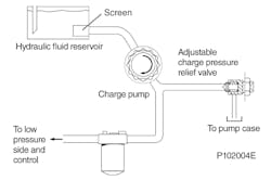
In suction line filtration, a filter is placed in the circuit between the fluid reservoir and the inlet to the closed-circuit pump. Follow the manufacturer’s recommendations for bypass versus non-bypass filter in the suction line. A vacuum gauge can be used to show when the inlet pressure exceeds the manufacturer’s requirements. A contamination monitor will indicate when a filter change is needed, once a maximum vacuum level is reached.
Examinations have revealed that a filter in the suction line with a β35 – β45 = 75 (β10 ≥2) at a differential pressure of 0.25bar achieves the required cleanliness of 18/13 under normal operating conditions. In some applications even better cleanliness levels are achieved.
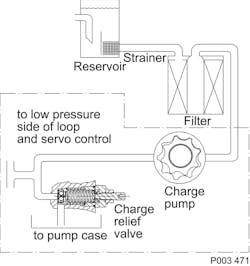
In charge pressure filtration, the filter is designed into the charge circuit of the closed-circuit pump. Placing the filter in the charge circuit can mitigate high inlet vacuum during cold start-up conditions. Fluid filtration is provided immediately ahead of a pump’s control and the hydraulic loop.
Examinations here, too, have shown that filter elements with a β15 – β20 = 75 (β10 ≥ 10)Partial Versus Full Flow Charge Filtration
The charge pressure filtration design can be further broken down into either partial flow or full flow.
Partial flow filtration refers to the charge pressure relief valve located upstream of the filtration. A portion of the charge pump oil flows through the filter while the rest flows over the charge pressure relief valve back to the reservoir. Only the fluid needed by the closed loop system and the pump control is filtered.
Carefully consider whether to use a non-bypass or bypass filter, as excessive pressure drops can occur that may lead to charge pump damage as well as contaminants being forced through the filter media. A “loop flushing” valve in the circuit increases the volume of “dirty” fluid being removed from the system and, consequently, increases the volume of fluid passing through the filter.
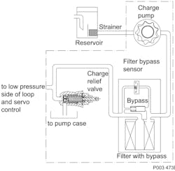
Full flow filtration has the charge pressure relief valve downstream of the filter element. All the charge pump flow is passed through the filter increasing the filter efficiency compared to suction filtration.
With full flow filtration, a bypass valve can prevent filter damage and contaminants from being forced through the filter media by high pressure differentials across the filter. Fluid will bypass the filter with a high pressure drop or cold start-up condition. Operating the system with an open bypass should be avoided, and a means of contamination indication is recommended.
Open-Circuit Designs
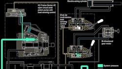
In contrast to closed-circuit hydraulic systems, suction filtration is not a recommended filtration method with open-circuit pumps. This is due to the potential for high inlet vacuum to occur. Instead, a screen is recommended in the reservoir covering the pump inlet. A 125 µm (150 mesh) screen protects the pump from course particle ingression.
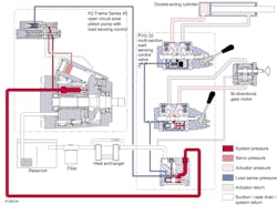
Return line filtration, with the filter in the return line to the reservoir, is often the preferred method in open-circuit systems. All the fluid in the system passes through the filter as it returns to the reservoir.
Factors to consider when specifying a return line filter system are:
- Cleanliness specification
- Contaminant ingression rates
- Flow capacity
- Desired maintenance interval
Typically, a filter with a β10 ≥ 10 is adequate.
Maintaining a Filtration System
As this article serves only as a guideline, it is imperative to work closely with the filter manufacturer when selecting a filter. Every open- and closed-circuit hydraulic system is unique, and the filtration requirements and performance must be determined by test.
It is essential that monitoring of prototype systems and evaluation of components and performance throughout the test program be the final criteria for judging the adequacy of the filtration system.
John Fleming is a principal engineer at Danfoss Power Solutions.
